The-Notebook

My notes on life

View on GitHub

Network Security and Data Communications

WTAMU CIDM-3385

Table of Contents:

The OSI Model

The Open Systems Interconnection (OSI) model is a theoretical way of classifying and talking about the complex process of sending data on a network. You should be familiar with the OSI model because it is the most widely used method for understanding and talking about network communications. However, remember that it is only a theoretical model that defines standards for programmers and network administrators, not a model of actual physical layers.

OSI Model Benefits

The OSI model:

OSI Model Limitations

However, you must remember the following limitations of the OSI model:

The following table compares the functions performed at each OSI model layer.

Layer Description and Keywords
Application (Layer 7) The Application layer integrates network functionality into the host operating system and enables communication between network clients and services. The Application layer does not include specific applications that provide services, but rather provides the capability for services to operate on the network.

Most Application layer protocols operate at multiple layers down to the Session and even Transport layers. However, these protocols are classified as Application layer protocols because they start at the Application layer (the Application layer is the highest layer where they operate). Services typically associated with the Application layer include:

  • HTTP
  • Telnet
  • FTP
  • TFTP
  • SNMP
Presentation (Layer 6) The Presentation layer formats, or presents, data in a compatible form for receipt by the Application layer or the destination system. Specifically, the Presentation layer ensures:
  • Formatting and translation of data between systems.
  • Negotiation of data transfer syntax between systems by converting character sets to the correct format.
  • Encapsulation of data into message envelopes by encryption and compression.
  • Restoration of data by decryption and decompression.
Session (Layer 5) The Session layer manages the sessions in which data are transferred. Session layer functions include:
  • Management of multiple sessions (each client connection is called a session). A server can concurrently maintain thousands of sessions.
  • Assignment of a session ID number to each session to keep data streams separate.
  • The setup, maintenance, and teardown of communication sessions.
Transport (Layer 4) The Transport layer provides a transition between the upper and lower layers of the OSI model, making the upper and lower layers transparent from each other. Transport layer functions include:
  • End-to-end flow control.
  • Port and socket numbers.
  • Segmentation, sequencing, and combination.
  • Connection services, either reliable (connection-oriented) or unreliable (connectionless) delivery of data.
At the Transport layer, data segments are called segments.
Network (Layer 3) The Network layer describes how data is routed across networks and on to the destination. Network layer functions include:
  • Identifying hosts and networks by using logical addresses.
  • Maintaining a list of known networks and neighboring routers.
  • Determining the next network point where data should be sent. Routers use a routing protocol that takes various factors into account, such as the number of hops in the path, link speed, and link reliability, to select the optimal path for data.
At the Network layer, data segments are called packets.
Data Link (Layer 2) Logical Link Control (LLC) The Data Link layer defines the rules and procedures for hosts as they access the Physical layer. These rules and procedures define:
  • How physical network devices are identified on the network by defining a unique hardware address (physical or MAC address).
  • How and when devices have access to the LAN and can transmit on the network medium (media access control and logical topology).
  • How to verify that the data received from the Physical layer is error free (parity and CRC).
  • How devices control the rate of data transmission between hosts (flow control).
At the Data Link layer, data segments are called frames. Switches, bridges and NICs, and WAPs function in Layer 2.
Media Access Control (MAC)
Physical (Layer 1) The Physical layer of the OSI model sets standards for sending and receiving electrical signals between devices. Protocols at the Physical layer identify:
  • How digital data (bits) are converted to electric pulses, radio waves, or pulses of light and moved across network cables.
  • Specifications for cables and connectors.
  • The physical topology.
At the Physical layer, data segments are called bits. NICs, repeaters, hubs, WAPs, and modems function in Layer 1.

TCP/IP Model Layers

The TCP/IP model incorporates the general concepts and structure of the OSI model. The layers of the TCP/IP model are as follows:

Layer Description
Application The Application layer corresponds to the Session, Presentation, and Application layers of the OSI model. Protocols associated with the Application layer include FTP, HTTP, Telnet, SMTP, DNS, and SNMP.
Host-to-Host The Host-to-Host layer is comparable to the Transport layer of the OSI model. It is responsible for error checking and reliable packet delivery. Here, the data stream is broken into segments that must be assigned sequence numbers so they can be reassembled correctly on the remote side after they are transported. Protocols associated with the Host-to-Host layer include Transport Control Protocol (TCP) and User Datagram Protocol (UDP).
Internet The Internet layer is comparable to the Network layer of the OSI model. It is responsible for moving packets through a network. This involves addressing hosts and making routing decisions to identify how the packet traverses the network. Protocols associated with the Internet layer include Address Resolution Protocol (ARP), Internet Control Message Protocol (ICMP), and the Internet Group Management Protocol (IGMP).
Network Access The Network Access layer corresponds to the Physical and Data Link layers of the OSI model. It is responsible for describing the physical layout of the network and formatting messages on the transmission medium.
The TCP/IP model focuses specifically on the functions in the Internet layer and Host-to-Host layers. All other functions of the traditional OSI model are encompassed in the first and fourth layers.

Mnemonic Device For Layers

To help remember the layer names of the OSI model, try the following mnemonic devices:

Layer Name Mnemonic
(Bottom to top)
Mnemonic
(Top to bottom)
Layer 7 Application Away All
Layer 6 Presentation Pizza People
Layer 5 Session Sausage Seem
Layer 4 Transport Throw To
Layer 3 Network Not Need
Layer 2 Data Link Do Data
Layer 1 Physical Please Processing

Have some fun and come up with your own mnemonic for the OSI model, but stick to one so you don't get confused.


Chapter 5 IP Addressing

Back to top

As you study this section, answer the following questions:

  • What is an octet?
  • What is the decimal equivalent of the following binary number? 01100111. What is the binary equivalent of the following decimal number? 211.
  • How is the network portion of an IP address identified?
  • Which portion of a class C address designates the network address?
  • What is the difference between subnetting and supernetting? Which method uses a subnet mask that is longer than the default subnet mask?
  • What does /14 mean in the following IP address: 199.78.11.12/14?
  • How does variable-length subnet masking work?

In this section, you will learn to:

  • Configure IP addresses.
  • Configure IP addresses on mobile devices.
5

The key terms for this section include:

Term Definition
IANA The Internet Assigned Numbers Authority is a function of a nonprofit private American corporation that oversees global IP address allocation, autonomous system number allocation, root zone management in the Domain Name System, media types, and other Internet Protocol-related symbols and internet numbers.
Classful IP Addresses Classful addresses are IP addresses that use a default subnet mask, as follows:
  • Class A: 255.0.0.0
  • Class B: 255.255.0.0
  • Class C: 255.255.255.0
VLSM Variable Length Subnet Masking (VLSM) is the method used to divide an IP address into subnets of different sizes. When using VLSM, you ignore the default subnet mask boundaries and specify a custom number of subnet mask bits.
Subnetting The process of dividing a large network into smaller networks.
Supernetting The process of combining two or more networks.
Classless Inter-Domain Routing
(CIDR)
A set of internet protocol standards used to create unique identifiers for networks and host devices.
ANDing The process used to determine the network address/ID.
Subnet Mask A 32-bit number that defines which portion of an IPv4 address identifies the network address and which portion of the address defines the host address.
Network ID A 32-bit number that identifies the network an IPv4 address belongs to.

IP Addresses

IP addresses allow hosts to participate on IP-based networks. The following are important things to know about IP addresses:

  • An IP address is a 32-bit binary number represented as four octets (four 8-bit-numbers). Each octet is separated by a period.
  • IP addresses can be represented two different ways:
    • Decimal (e.g., 131.107.2.200). In decimal notation, each octet must be between 0 and 255.
    • Binary (e.g., 10000011.01101011.00000010.11001000). In binary notation, each octet is an 8-character number.
  • To convert from binary to decimal, memorize the decimal equivalent to the following binary numbers:
    10000000 01000000 00100000 00010000 00001000 00000100 00000010 00000001
    128 64 32 16 8 4 2 1
    Add together the decimal values of each bit position with a 1 value. For example, the decimal equivalent of 10010101 is:
    128 + 16 + 4 + 1 = 149
  • The IP address includes both the network and the host address.
  • A subnet mask is a 32-bit number associated with an IP address that identifies the network portion of the address. In binary form, the subnet mask is always a series of 1s followed by a series of 0s (1s and 0s are never mixed in sequence in the mask). A simple mask might be 255.255.255.0 (i.e., 11111111.11111111.11111111.00000000).
  • IP addresses have a default class. The address class identifies the range of IP addresses and the default subnet mask used for the range. The following table shows the default address class for each IP address range:
    Class Address Range First Octet Range Default Subnet Mask
    A 1.0.0.0 to 126.255.255.255 1–126
    (00000001–01111110 binary)
    255.0.0.0
    B 128.0.0.0 to 191.255.255.255 128–191
    (10000000–10111111 binary)
    255.255.0.0
    C 192.0.0.0 to 223.255.255.255 192–223
    (11000000–11011111 binary)
    255.255.255.0
    D 224.0.0.0 to 239.255.255.255 224–239
    (11100000–11101111 binary)
    n/a
    E 240.0.0.0 to 255.255.255.255 240–255
    (11110000–11111111 binary)
    n/a
  • When using the default subnet mask for an IP address, you have the following number of subnet addresses and hosts per subnet:
    • There are only 126 Class A network IDs (most of these addresses are already assigned). Each class A address gives you 16,777,214 hosts per network.
    • There are 16,384 Class B network IDs. Each class B address gives you 65,534 hosts per network.
    • There are 2,097,152 Class C network IDs. Each class C address gives you 254 hosts per network.
    • Class D addresses are used for multicast groups rather than network and host IDs.
    • Class E addresses are reserved for experimental use.

Special Considerations

As you are assigning IP addresses to hosts, think of the following special considerations:

Address Consideration
Network The first address in an address range is used to identify the network itself. For the network address, the host portion of the address contains all 0s. For example:
  • Class A network address: 115.0.0.0
  • Class B network address: 154.90.0.0
  • Class C network address: 221.65.244.0
Broadcast The last address in the range is the broadcast address, and it is used to send messages to all hosts on the network. In binary form, the broadcast address has all 1s in the host portion of the address. For example, assuming the default subnet masks are used:
  • 115.255.255.255 is the broadcast address for network 115.0.0.0
  • 154.90.255.255 is the broadcast address for network 154.90.0.0
  • 221.65.244.255 is the broadcast address for network 221.65.244.0
The broadcast address might also be designated by setting each of the network address bits to 0. For example, 0.0.255.255 is the broadcast address of a Class B address. This designation means "the broadcast address for this network."
Host Addresses When you are assigning IP addresses to hosts, understand the following:
  • Each host must have a unique IP address.
  • Each host on the same network must have an IP address with a common network portion of the address. You must use the same subnet mask when configuring addresses for hosts on the same network.
The range of IP addresses available for network hosts is identified by the subnet mask and/or the address class. When assigning IP addresses to hosts, be aware that you cannot use the first or last addresses in the range (these are reserved for the network and broadcast addresses respectively). For example:
  • For the class A network address 115.0.0.0, the host range is 115.0.0.1 to 115.255.255.254.
  • For the class B network address 154.90.0.0, the host range is 154.90.0.1 to 154.90.255.254.
  • For the class C network address 221.65.244.0, the host range is 221.65.244.1 to 221.65.244.254.
Another way to identify a host on a network is to set the network portion of the address to all 0s. For example, the address 0.0.64.128 means "host 64.128 on this network."
Local Host Addresses in the 127.0.0.0 range are reserved to refer to the local host (the host you're currently working at). The most commonly used address is 127.0.0.1, which is the loopback address.

Because IP addresses assigned to hosts must be unique, the use of IP addresses on the internet is controlled by organizations that ensure that every organization is given its own range of IP addresses to assign to hosts:

  • The Internet Assigned Numbers Authority (IANA) manages the assignment of IP addresses on the internet. IANA is operated by the Internet Corporation for Assigned Names and Numbers (ICANN).
  • IANA allocates blocks of IP addresses to Regional Internet Registries (RIRs). An RIR has authority over IP addresses in a specific region of the world.
  • An RIR assigns blocks of addresses to Internet Service Providers (ISPs).
  • An ISP assigns one or more IP addresses to individual computers or organizations connected to the Internet.

</br>

Subnetting

Subnetting is the process of dividing a large network into smaller networks called subnets. When you subnet a network, each network segment has a different network address, or subnet address. In practice, the terms network and subnet are used interchangeably to describe a physical network segment with a unique network address.

Functions of Subnetting

From a physical standpoint, subnetting is necessary because network architectures impose a limit on the number of hosts allowed on a single network segment. As your network grows, you will need to create subnets (physical networks) to:

  • Increase the number of devices that can be added to the LAN (to overcome the architecture limits)
  • Decrease the number of devices on a single subnet (to reduce traffic congestion)
  • Reduce the processing load placed on computers and routers
  • Isolate sensitive systems on the network

Subnetting is also used to efficiently allocate available IP addresses. For example, an organization with a class B network ID is allocated enough addresses for 65,536 hosts. However, if the organization in practice uses only 10,000 of those host IDs, over 55,000 IP addresses are going unused. Subnetting provides a way to break the single class B network ID into multiple smaller network IDs.

  • Subnetting uses custom subnet masks instead of the default subnet masks (e.g., using 255.255.255.0 with a Class B address instead of the default 255.255.0.0).
  • When you subnet a network by using a custom mask, you can divide the IP addresses between several subnets. However, you also reduce the number of hosts available on each network.
  • Using custom subnet masks is often called classless addressing because the subnet mask cannot be inferred simply from the class of a given IP address. The address class is ignored, and the mask is always supplied to identify the network and host portions of the address.

The following table shows how a Class B address can be subnetted to provide additional subnet addresses. Notice that by using a custom subnet mask, the Class B address looks like a Class C address.

Subnetting Class B Addresses

Default Example Custom Example
Network Address 188.50.0.0 188.50.0.0
Subnet Mask 255.255.0.0 255.255.255.0
# of Subnet Addresses One 254
# of Hosts per Subnet 65,534 254 per subnet
Subnet Address(es) 188.50.0.0 (only one) 188.50.1.0
188.50.2.0
188.50.3.0
(and so on)
Host Address Range(s) 188.50.0.1 to 188.50.255.254 188.50.1.1 to 188.50.1.254
188.50.2.1 to 188.50.2.254
188.50.3.1 to 188.50.3.254
(and so on)

Remember that the last valid host address ends with 254 because 255 is a broadcast address and is not available as a host address. For example:

  • For the class A network address 115.0.0.0, the host range is 115.0.0.1 to 115.255.255.254.
  • For the class B network address 154.90.0.0, the host range is 154.90.0.1 to 154.90.255.254.
  • For the class C network address 221.65.244.0, the host range is 221.65.244.1 to 221.65.244.254.
While subnetting divides a large address space into multiple subnets, supernetting combines multiple small network addresses into a single larger network. Supernetting allows multiple Class C addresses to be combined into a single network.

Variable Length Subnet Masking (VLSM)

Classful IP Addresses

Classful addresses are IP addresses that use a default subnet mask, as follows:

  • Class A: 255.0.0.0
  • Class B: 255.255.0.0
  • Class C: 255.255.255.0

They are considered classful because the default subnet mask identifies the network portion and host portion of the IP address.

Classless IP Addresses

Classless addresses, on the other hand, use a custom mask value to separate the network and host portions of the IP address. Classless addressing is made possible using Classless Inter-Domain Routing (CIDR). CIDR allows you to use only part of an octet for the network address. This is called partial subnetting, or variable-length subnet masking (VLSM).

VLSM - Variable Length Subnet Masking

When using VLSM, you ignore the default subnet mask boundaries and specify a custom number of subnet mask bits. For example, you could define a subnet mask of 255.255.252.0. In addition to the first and second octets, this mask also assigns the first six bits in the third octet to be used for the network portion of the address. This mask would appear in binary notation as follows:

11111111.11111111.11111100.00000000

As you can see, the six bits are reallocated from the host address to the network address. This allows you to create additional subnets, but it reduces the number of host addresses available within each one.

For example, suppose your network is composed of four separate physical network segments connected by routers. The network uses the 10.0.0.0 private IP addressing scheme, but you want to divide the 10.0.0.0 network into four separate subnets. Under classful addressing, this network would use the first octet for the network address and the last three octets for node addresses. However you need to divide this large network into four subnets. To do this, you need to reconfigure the subnet mask to include the first two bits of the second octet, creating four additional networks. Instead of using the default Class A subnet mask of 11111111.00000000.00000000.00000000 (255.0.0.0), you use a subnet mask of 11111111.11000000.00000000.00000000 (255.192.0.0). Using CIDR notation, you can specify a prefix of /10 to indicate you are using 10 bits for the subnet mask.

The following are four possible values in the IP address for the two extra bits that have been added to the subnet mask:

  • 00 = 0
  • 01 = 64
  • 10 = 128
  • 11 = 192

These values define the lower and upper boundaries for the four subnets created by the classless subnet mask, as shown in the following table:

Subnet Address Subnet Mask Subnet Host Address Range Subnet Broadcast Address
10.0.0.0 255.192.0.0 10.0.0.1–10.63.255.254 10.63.255.255
10.64.0.0 255.192.0.0 10.64.0.1–10.127.255.254 10.127.255.255
10.128.0.0 255.192.0.0 10.128.0.1–10.191.255.254 10.191.255.255
10.192.0.0 255.192.0.0 10.192.0.1–10.255.255.254 10.255.255.255
On the internet, you can access many subnet calculators  to calculate subnet boundaries, host addresses, and broadcast addresses.

IP Address Assignment

The following table lists several options for assigning IP addresses.

Method Uses
Dynamic Host Configuration Protocol (DHCP) A DHCP server is a special server configured to pass out IP addresses and other IP configuration information to network clients. DHCP servers ensure that each client is assigned a unique IP address.
  • When a DHCP client system boots, it contacts the DHCP server for IP configuration information. The DHCP server is configured with a range of IP addresses it can assign to hosts. These ranges are called scopes.
    • The DHCP server can be configured to prevent specific addresses in the range from being assigned to clients. This is called an exclusion.
    • You can also configure a DHCP server to deliver the same address to a specific host each time it requests an address. This is called a reservation.
  • The DHCP server can also be configured to pass out other IP configuration information, such as the default gateway and DNS server addresses.
  • The DHCP server assigns the IP address and other information to the client. The assignment is called a lease, and it includes a lease time that identifies how long the client can use the IP address.
    • Periodically, the client contacts the DHCP server to renew the lease on the IP address. The client will also attempt to renew the lease on the same IP address if it reboots.
    • The DHCP lease process uses broadcast frames at Layer 2. For this reason, DHCP requests do not pass through routers to other subnets by default. To enable DHCP broadcasts between subnets, enable IP helper or DHCP relay on the appropriate routers.
    • When the lease expires, the DHCP server releases the reserved IP address. This is known as the expired IP address.
  • Any client configured to use DHCP can get an IP address from any server configured for DHCP, regardless of its operating system.
DHCP is the preferred IP configuration method for small, medium, and large networks.
Static (Manual) Assignment Static addressing means that IP configuration information is manually configured on each host. Static addressing is best used in the following situations:
  • On networks with a very small number of hosts.
  • On networks that do not change often or that will not grow.
  • To permanently assign IP addresses to hosts that must always have the same address (such as printers, servers, or routers).
  • For hosts that cannot accept IP addresses from DHCP servers.
  • To reduce DHCP-related traffic.
Static addressing is very susceptible to configuration errors and duplicate IP address configuration errors. Static addressing disables both APIPA and DHCP functions on the host.

APIPA and Alternate IP Addressing

As you study this section, answer the following questions:

  • How do you know if a host is using an APIPA address?
  • Which IP configuration parameters are set when APIPA is used? Which parameters are not set?
  • In which scenarios would an alternate IP configuration simplify IP configuration?

In this section, you will learn to:

  • Set Up alternate addressing.
  • Configure alternate addressing.

The key terms for this section include:

Term Definition
Automatic Private IP Addressing (APIPA) APIPA provides an option for automatic IP address assignment without a DHCP server. APIPA is enabled by default on most modern operating systems, including Windows and Linux.
Alternate IP Configuration A manual configuration of a computer's IP address, default gateway, DNS server address, and WINS address. This configuration is used if the DHCP server fails to provide this similar information.

If a host is configured to obtain its IP address from a DHCP server but that server is unreachable, then an alternate IP address assignment method may be employed as follows:

Method Description
Automatic Private IP Addressing (APIPA) APIPA provides an option for automatic IP address assignment without a DHCP server. APIPA is enabled by default on most modern operating systems, including Windows and Linux.

Using APIPA, hosts can assign themselves an IP address on the 169.254.0.0 network (with a mask of 255.255.0.0) if they can't locate a DHCP server. If a network host is configured to use dynamic IP addressing and a DHCP server can't be contacted, APIPA assigns a temporary IP address to the host. However, only the IP address and mask are assigned. Default gateway and DNS server addresses are not assigned. For this reason, APIPA can be used only to enable communications within a single subnet. Communication with other networks, including the internet, are not possible. In addition, communication with network infrastructure devices that use static IP addressing, such as servers, is not possible even if they are on the same local subnet as the APIPA host.

Alternate IP Configuration With an alternate IP configuration, static IP configuration values are used if a DHCP server cannot be contacted. When you configure an alternate IP address, APIPA is automatically disabled. It is recommended that you use an IP configuration other than APIPA because you hosts need to access other systems on the local subnet and on other networks, including the internet. Alternate IP configuration also allows continued access to servers and other network infrastructure devices that use static IP addresses.

DHCP Server Configuration

As you study this section, answer the following questions:

  • What type of configuration parameters can be delivered using DHCP?
  • What are the advantages of static IP address assignments?
  • When might you want to use static IP addressing?

In this section, you will learn to:

  • Configure a DHCP server.
  • Configure DHCP options.
  • Create DHCP exclusions.
  • Create DHCP client reservations.
  • Configure a DHCP client.

The key terms for this section include:

Term Definition
DHCP Discover (D) The client begins by sending out a DHCP Discover frame to identify DHCP servers on the network.
DHCP Offer (O) A DHCP server that receives a Discover request from a client responds with a DHCP Offer advertisement, which contains an available IP address. If more than one DHCP server responds with an offer, the client usually responds to the first offer it receives.
DHCP Request (R) The client accepts the offered IP address by sending a DHCP request back to the DHCP server.
DHCP ACK (A) The DHCP server responds to the request by sending a DHCP ACK (acknowledgement). At this point, the IP address is leased to and configured on the DHCP client.

The dynamic host configuration protocol (DHCP) centralizes management of IP addressing in a network by allowing a server to dynamically assign IP addresses to clients. DHCP also allows mobile users, who move from network to network, to easily obtain an IP address appropriate for each network they connect to.

Obtain an Address from a DHCP Server

Because a DHCP client doesn't have an IP address when it initially boots, it must use broadcast frames to communicate with a DHCP server. The table below describes the method used to obtain an address from a DHCP server.

Broadcast Description
DHCP Discover (D) The client begins by sending out a DHCP Discover frame to identify DHCP servers on the network.
DHCP Offer (O) A DHCP server that receives a Discover request from a client responds with a DHCP Offer advertisement, which contains an available IP address. If more than one DHCP server responds with an offer, the client usually responds to the first offer that it receives.
DHCP Request (R) The client accepts the offered address by sending a DHCP request back to the DHCP server. If multiple offers were sent, the DHCP request message from the client also informs the other DHCP servers that their offers were not accepted and the IP addresses contained in their offers can be made available to other clients.
DHCP ACK (A) The DHCP server responds to the request by sending a DHCP ACK (acknowledgement). At this point, the IP address is leased to and configured on the DHCP client.
If the DHCP server is on a different subnet, additional configuration steps are required, since network routers drop the DHCP broadcast frames by default.

Configuring a DHCP Server

Keep in mind the following when configuring a DHCP Server:

  • The DHCP service needs to auto-start when the server boots.
  • The server must have a static IP address.
  • A MAC reservation is an association of a MAC address with a specific IP address. In other words, the client with the specified MAC address is assigned the same IP address each time it requests an address.
  • An IP reservation means you program MAC addresses into the DHCP server. When the DHCP server sees a certain host requesting an IP address based on its MAC, it will give you a specific IP address.

For a DHCP server to deliver IP addresses, it must have a scope configured. A scope is the range of IP addresses that the DHCP server can assign to clients. A scope can also be called a pool. When working with scopes, remember the following:

  • There should be only one scope per network segment.
  • The scope must be activated before the DHCP server can assign addresses to clients. After you activate a scope, you should not change it.
  • A scope has a subnet mask that determines the subnet for a given IP address. You cannot change the subnet mask of an existing DHCP scope; to change the subnet mask used by a scope, you must delete and recreate the scope.
  • Lease duration values are part of the scope properties, and they determine the length of time a client can use an IP address leased through DHCP.
The DHCP server can also be configured with exclusions, which are specific addresses in the range that should not be assigned.

DHCP Server Functions

In addition to providing IP addresses, a DHCP server can also provide clients with additional IP configuration parameters using options. Commonly used DHCP options include the subnet mask, the default gateway address, and a DNS server address. The following levels of options can be configured:

  • Server options are applied to all computers that get an IP address from the DHCP server, regardless of which scope they obtain the address from (for example, if your organization has only one DNS server, then all DHCP clients need the same DNS server address.)
  • Scope options are applied to all computers that get an IP address from a particular scope on the DHCP server (for example, because scopes are associated with specific subnets, each scope needs to be configured with the appropriate default gateway address option.)
  • Client options are applied to a specific DHCP client. The client's MAC address is used to identify which system receives the option.

The DHCP console provides context-sensitive icons to reflect DHCP server status as follows:

  • A check mark in a green circle indicates that the DHCP server is connected and authorized.
  • A red down arrow indicates that the DHCP server is connected, but not authorized.
  • A horizontal white line inside a red circle indicates that the DHCP server is connected, but the current user does not have the administrative credentials necessary to manage the server.
  • An exclamation point inside a yellow triangle indicates that 90% of available addresses for server scopes are either in use or leased.
  • An exclamation point inside a blue circle indicates that 100% of available addresses for server scopes are either in use or leased.

DHCP Relay

As you study this section, answer the following questions:

  • What is the difference between an RFC 1542 compliant router and a DHCP relay agent?

In this section, you will learn to:

  • Configure a DHCP relay agent
  • Add a DHCP server on another subnet

The key terms for this section include:

Term Definition
RFC 1542 Compliant Router An RFC 1542 compliant router listens for DHCP traffic and routes any received DHCP frames to the appropriate subnet. .
DHCP Relay Agent A function of the Routing and Remote Access service (RRAS) role on a Windows server, the DHCP Relay Agent service sends the DHCP packets it receives to a remote DHCP server on a different subnet.

Because a DHCP client doesn't have an IP address assigned when it initially boots, it must use broadcast frames to communicate with a DHCP server. If the server is on a different subnet than the client, then the DHCP requests sent by the client will not reach the server because broadcast frames are dropped by network routers. If your network is configured in this manner, you can implement one of the following mechanisms to forward DHCP broadcasts through network routers to a remote DHCP server on a different subnet:

Option Description
RFC 1542 Compliant Router An RFC 1542 compliant router listens for DHCP traffic and routes any received DHCP frames to the appropriate subnet. For example, on a Cisco router, you can enable this functionality by using the ip helper-address command. The syntax is:
ip helper-address [server_address]
Replace [server_address] with the IP address of the remote DHCP server.
DHCP Relay Agent If you use a Windows server in your network, then you can install the Routing and Remote Access service (RRAS) role on the server and enable the DHCP Relay Agent Role service. The DHCP Relay Agent service sends the DHCP packets it receives to a remote DHCP server on a different subnet. To configure the DHCP Relay service, you must:
  • Specify which server network interface the agent listens on for DHCP messages.
  • Specify the IP address of the remote DHCP server the agent should forward DHCP messages to.

DNS Name Resolution

As you study this section, answer the following questions:

  • How are host names organized in DNS?
  • What is the difference between a forward lookup zone and a reverse lookup?
  • What is the role of the root servers in DNS?
  • In DNS, what is the difference between a zone and a domain?
  • What is the difference between an A record and a PTR record?

In this section, you will learn to:

  • Configure DNS addresses.
  • Create standard DNS zones.
  • Create reverse DNS zones.
  • Create host records.
  • Create CNAME records.
  • Troubleshoot DNS records.

The key terms for this section include:

Term Definition
. (dot) domain The . (dot) domain, or root domain, denotes a fully qualified, unambiguous domain name.
Top-Level Domain
(TDL)
The last part of a domain name (for example, .com, .edu, .gov). TDLs are managed by the Internet Corporation of Assigned Names and Numbers (ICANN).
Fully Qualified Domain Name
(FQDN)
The host name and all domain names separated by periods. The final period (which is for the root domain) is often omitted and only implied.
Additional Domains Additional domains are second-level domains with names registered to an individual or organization for use on the internet. These names are based on an appropriate top-level domains, depending on the type of organization or geographic location where a name is used. Yahoo.com and microsoft.com are examples of additional domains in your DNS structure.
Hostname The hostname is the part of a domain name that represents a specific host. For example, "www" is the hostname of www.example.com.
Records Records are used to store entries for hostnames, IP addresses, and other information in the zone database. Each host has at least one record in the DNS database that maps the hostname to the IP address.
Authoritative Server An authoritative server is a DNS server that has a complete copy of all the records for a particular domain.
Dynamic DNS
(DDNS)
DDNS enables clients or the DHCP server to update records in the zone database. Without dynamic updates, all A (host) and PTR (pointer) records must be configured manually. With dynamic updates, host records are created and deleted automatically whenever the DHCP server creates or releases an IP address lease.

The Domain Name System (DNS) is a hierarchical distributed database that maps logical host names to IP addresses. DNS is a distributed database because no one server holds all of the DNS information. Instead, multiple servers hold portions of the data as follows:

  • Each division of the database is held in a zone database file.
  • Zones typically contain one or more domains, although additional servers might hold information for child domains.
  • DNS servers hold zone files and process name resolution requests from client systems.
     

Parts of a DNS
The DNS is made up of the following components:

Component Description
. (dot) domain The . (dot) domain, or root domain, denotes a fully qualified, unambiguous domain name.
Top-Level Domain (TLD) A TLD is the last part of a domain name (for example, .com, .edu, .gov). TLDs are managed by the Internet Corporation of Assigned Names and Numbers (ICANN).
Fully Qualified Domain Name (FQDN) The FQDN includes the host name and all domain names separated by periods. The final period (which is for the root domain) is often omitted and only implied.
Additional Domains
(Second-Level Domains)
Additional domains are second-level domains with names registered to an individual or organization for use on the internet. These names are based on an appropriate top-level domain, depending on the type of organization or geographic location where a name is used. Yahoo.com and microsoft.com are examples of additional domains in your DNS structure.
Host Name The host name is the part of a domain name that represents a specific host. For example, "www" is the host name of www.example.com.
Records Records are used to store entries for host names, IP addresses, and other information in the zone database. Each host has at least one record in the DNS database that maps the host name to the IP address. Common resource records include:
  • The A (Host Address) record maps an IPv4 (32-bit) DNS host name to an IP address. This is the most common resource record type.
  • The AAAA (Quad-A) record maps an IPv6 (128-bit) DNS host name to an IP address.
  • The PTR (Pointer) record maps an IP address to a host name (by pointing to an A record).
  • The MX (Mail Exchanger) record identifies servers that can be used to deliver email.
  • The CNAME (Canonical Name) record provides alternate names (or aliases) to hosts that already have a host record. If you only use a single A record with multiple CNAME records, when the IP address changes, you only have to modify the A record.
  • The NS (Name Server) resource record identifies all name servers that can perform name resolution for the zone. Typically, there is an entry for the primary server and all secondary servers for the zone (all authoritative DNS servers).
  • The SRV (Service Locator) record identifies the resources that provide a service. This allows clients to find services, such as domain controllers, through DNS. Windows automatically creates these records as needed.
  • The SPF (Sender Policy Framework) record identifies authorized email servers. SPF records are created using TXT records. DNS uses the SPF record to verify that the host that sent the mail is authorized to use the DNS name.
  • DKIM (Domain Keys Identified Mail) is an email authentication method that uses a digital signature to validate email and make it easier to identify spoofed emails. The sending mail server signs the email with the private key, and the receiving mail server uses the public key in the domain's DNS information to verify the signature. One domain can have several DKIM keys publicly listed in DNS, but each matching private key is only on one mail server. DKIM records are created using TXT records.
Authoritative Server An authoritative server is a DNS server that has a complete copy of all the records for a particular domain.
Dynamic DNS (DDNS) DDNS enables clients or the DHCP server to update records in the zone database. Without dynamic updates, all A (host) and PTR (pointer) records must be configured manually. With dynamic updates, host records are created and deleted automatically whenever the DHCP server creates or releases an IP address lease. Dynamic updates occur when:
  • A network host's IP address is added, released, or changed.
  • The DHCP server changes or renews an IP address lease.
  • The client's DNS information is manually changed using ipconfig /registerdns.

Recursion Process
When you use the host name of a computer (for example, if you type a URL such as www.mydomain.com), recursion is employed to find the IP address. Recursion is the process by which a DNS server uses root name servers and other DNS servers to perform name resolution. The following steps occur:

  1. The host looks in its local cache to see if it has recently resolved the host name.
  2. If the information is not in the cache, it checks the Hosts file. The Hosts file is a static text file that contains host-name-to-IP address mappings.
  3. If the IP address is not found, the host contacts its preferred DNS server. If the preferred DNS server can't be contacted, the host continues contacting additional DNS servers until one responds.
  4. The host sends the name information to the DNS server. The DNS server checks its cache and Hosts file. If the information is not found, the DNS server checks any zone files that it holds for the requested name.
  5. If the DNS server can't find the name in its zones, it forwards the request to a root zone name server. This server returns the IP address of a DNS server that has information for the corresponding top-level domain (such as .com).
  6. The first DNS server requests the information from the top-level domain server. The server returns the address of a DNS server with the information for the next highest domain. This process continues until a DNS server is contacted that holds the necessary information.
  7. The DNS server places the information in its cache and returns the IP address to the client host. The client host also places the information in its cache and uses the IP address to contact the desired destination device.

DNS Facts
The following are some additional facts about DNS:

  • A forward lookup finds the IP address for a given host name. A reverse lookup finds the host name from a given IP address.
  • Root DNS servers hold information for the root zone ( . ). Root servers answer name resolution requests by supplying the address of the corresponding top-level DNS server (servers authoritative for .com, .edu, and similar domains).
  • On very small networks, you could configure a HOSTS file with several entries to provide limited name resolution services. However, you would have to copy the HOSTS file to each client. The work involved in this solution is only suitable for temporary testing purposes or for overriding information that might be received from a DNS server.
  • On the client, you should configure a list of DNS suffixes you want to append to unqualified DNS names submitted by clients for resolution as follows:
    • Configure a single DNS suffix for clients using a DHCP option on the DHCP server.
    • Configure multiple suffixes by adding them to the client manually.

IPV-6

As you study this section, answer the following questions:

  • What is the primary reason for developing IPv6?
  • How many hexadecimal numbers are in an IPv6 address? How does this compare to a MAC address?
  • What do you add to an IPv6 address when you remove one or more quartets with all 0s?
  • What information is included within the IPv6 address prefix?
  • How many numbers are used for the interface ID? How can the interface ID be related to the MAC address?
  • What is the difference between ISATAP and 6to4 tunneling?
  • What is the difference between stateful autoconfiguration and stateless autoconfiguration?

In this section, you will learn to:

  • Configure IPv6 addresses.
  • Configure a DHCP6 server.
  • Configure an IPv6 address.

The key terms for this section include:

Term Definition
Global-Unicast An IPv6 address type that is publicly routable and can be used in the internet.
Unique-Local An IPv6 address type that indicates an IP address is a private IP address.
Link-Local An IPv6 address type that indicates that the IP address was configured by default.
Multicast An IPv6 address type that indicates that the packet is addressed to a number of hosts on the network, but not all hosts.
Prefix ID The leftmost bits of the IPv6 address, also know as the network ID. The prefix is used for routing IPv6 packets.
Interface ID The rightmost bits of the IPv6 address used to uniquely identify a network card (interface) in a host.
Anycast A unicast address that is assigned to more than one interface, typically interfaces belonging to different hosts.
Local Loopback The local loopback address for the local host is 0:0:0:0:0:0:0:1 (also identified as ::1 or ::1/128). The local loopback address is not assigned to an interface. It can verify that the TCP/IP protocol stack is properly installed on the host.
Dual Stack A dual stack configuration enables a host to communicate with IPv4 and IPv6 hosts; the IPv4 and IPv6 protocol stacks run concurrently on a host.
Tunneling Tunneling allows IPv6 hosts or sites to communicate over the existing IPv4 infrastructure. A device encapsulates IPv6 packets within IPv4 packets for transmission across an IPv4 network, and then the IPv6 packets are de-encapsulated by another device at the other end.
Static Full Assignment The entire 128-bit address and all other configuration information is statically assigned to the host.
Static Partial Assignment The prefix is statically assigned. The interface ID is derived from the MAC address.
Stateless Autoconfiguration Clients automatically generate the interface ID and learn the subnet prefix and default gateway through the Neighbor Discovery Protocol (NDP).
DHCPv6 IPv6 uses an updated version of DHCP, DHCPv6. It operates in two modes, stateful and stateless.

The addresses available under the current IPv4 addressing standard have been exhausted. In response to this situation, a new IP addressing system (IP version 6, or IPv6) has been developed. An IPv6 address is a 128-bit binary number. A sample IPv6 IP address looks like the following: 35BC:FA77:4898:DAFC:200C:FBBC:A007:8973.

Features of an IPv6 Address

The following list describes the features of an IPv6 address:

  • It is made up of 32 hexadecimal numbers organized into 8 quartets.
  • The quartets are separated by colons.
  • Each quartet is represented as a hexadecimal number between 0 and FFFF. Each quartet represents 16 bits of data (FFFF = 1111 1111 1111 1111).
  • Leading zeros can be omitted in each section. For example, the quartet 0284 could also be written as 284.
  • An address with consecutive zeros can be expressed more concisely by substituting a double colon for the group of zeros. For example:
    • FEC0:0:0:0:78CD:1283:F398:23AB
    • FEC0::78CD:1283:F398:23AB (concise form)
      This is also called address compression. Address compression is when you take a fully-notated IPv6 address and remove empty octets from it, replacing them with a colon.
  • If an address has more than one consecutive location where one or more quartets are all zeros, only one location can be abbreviated. For example, FEC2:0:0:0:78CA:0:0:23AB can be abbreviated as:
    • FEC2::78CA:0:0:23AB
      or
    • FEC2:0:0:0:78CA::23AB
      but not
    • FEC2::78CA::23AB
  • The 128-bit address contains two parts:
    Component Description
    Prefix The first 64 bits are known as the prefix.
    • The prefix can be divided into various parts that identify things such as geographic region, the ISP, the network, and the subnet.
    • The prefix length identifies the number of bits in the relevant portion of the prefix. To indicate the prefix length, add a slash (/) followed by the prefix length number. Full quartets with trailing 0s in the prefix address can be omitted (e.g., 2001:0DB8:4898:DAFC::/64).
    • Because addresses are allocated based on physical location, the prefix generally identifies the location of the host. The 64-bit prefix is often referred to as the global routing prefix.
    Interface ID The last 64 bits are known as the interface ID. This is the unique address assigned to an interface.
    • Addresses are assigned to interfaces (network connections), not to the host. Technically, the interface ID is not a host address.
    • In most cases, individual interface IDs are not assigned by ISPs but are rather generated automatically or managed by site administrators.
    • Interface IDs must be unique within a subnet, but they can be the same if they are on different subnets.
    • On Ethernet networks, the interface ID can be automatically derived from the MAC address. Using the automatic host ID simplifies administration.

    To ensure that the interface ID is unique for every host on the network, IPv6 uses the Extended Unique Identifier 64 (EUI-64) format. The following are some details of the EUI-64 format:

    • Each host has a unique 48-bit hardware address called a MAC address (also called the burned-in address) that is assigned to each device by the vendor. The MAC address is guaranteed to be unique through design. The EUI-64 format uses the unique MAC address by:
      1. Splitting the MAC address into 24-bit halves.
      2. Inserting 16 bits (represented by hex FFFE) between the two halves.
        For example, a host with a MAC address of 20-0C-FB-BC-A0-07 would start with the following EUI-64 interface ID: 200C:FBFF:FEBC:A007.
      3. To be complete, the EUI-64 format requires setting the seventh bit in the first byte to binary 1 (reading from left to right, this is the second hex value in the interface ID). This bit is called the universal/local (U/L) bit.
        • When the U/L bit is set to 0, the MAC address is a burned-in MAC address.
        • When the U/L bit is set to 1, the MAC address has been configured locally. EUI-64 requires the U/L bit to be set to 1.
        Review the following examples:
        • 200C:FBFF:FEBC:A007 (Incorrect interface ID, as the U/L bit is still set to 0)
        • 220C:FBFF:FEBC:A007 (Correct interface ID)

IPv6 adds the following features not included in IPv4:

Feature Description
Auto-configuration Because hardware IDs are used for node IDs, IPv6 nodes simply need to discover their network IDs. This can be done by communicating with a router.
Built-in Quality of Service Built-in support for bandwidth reservations makes guaranteed data transfer rates possible. (Quality of service features are available as add-ons within an IPv4 environment but are not part of the native protocol.)
Built-in Security Features IPv6 has built-in support for security protocols such as IPsec. (IPsec security features are available as add-ons within an IPv4 environment.)
Source Intelligent Routing IPv6 nodes have the option to include addresses that determine part or all of the route a packet will take through the network.

IPv6, assigns addresses to interfaces (network connections). All interfaces require an IPv6 address, and each interface can have more than one IPv6 address. IPv6 defines the following types of addresses:

Address Type Description
Unicast Unicast addresses are assigned to a single interface for the purpose of allowing one host to send and receive data. Packets sent to a unicast address are delivered to the interface identified by that address.

There are three types of unicast IPv6 addresses:

Link-local Link-local addresses (also known as local link addresses) are only valid on the current subnet. Details include the following:
  • Link-local addresses have an FE80::/10 prefix. This includes any address beginning with FE8, FE9, FEA, or FEB.
  • All nodes must have at least one link-local address, although each interface can have multiple addresses.
  • Link-local addresses are used for automatic address configuration, for neighbor discovery, or for subnets that have no routers.
Do not use link-local IPv6 addressing on routed networks. Routers never forward packets destined for link-local addresses to other subnets.
Unique local Unique local addresses are private addresses used for communication within a site or between a limited number of sites. In other words, unique local addressing is commonly used for network communications that do not cross a public network; they are the equivalent of private addressing in IPv4. Details include the following:
  • Because unique local addresses are not registered with IANA, they cannot be used on a public network without address translation.
  • Addresses beginning with a prefix of FC00 or FD00 are unique local addresses.
  • Following the prefix, the next 40 bits are used for the Global ID. The Global ID is generated randomly, creating a high probability of uniqueness on the entire internet.
  • Following the Global ID, the remaining 16 bits in the prefix are used for subnet information.
  • Unique local addresses are likely to be globally unique, but they are not globally routable. Unique local addresses might be routed between sites by a local ISP.

The process for designing a network addressing scheme when using unique local addresses is similar to that used for global unicast addresses. The key difference is how the prefix is defined. Because the address range is not registered, a global routing prefix does not have to be requested from an ISP. Instead, each organization defines its own prefix.

Global unicast Global unicast addresses are assigned to individual interfaces that are globally unique. All IPv6 addresses that aren't specifically reserved for other purposes are defined as global unicast addresses. The global routing prefix assigned to an organization by an ISP is typically 48 bits long (/48), but it could be as short as /32 or as long as /56, depending on the ISP. All subnet IDs within the same organization must begin with the same global routing prefix, but they must also be uniquely identified using a different value in the subnet field.

Using this addressing scheme allows organizations to define a large number (216) of IPv6 subnets. When you design an IPv6 network, define separate IPv6 subnets by the following:

  • Network segments separated by routers
  • VLANs
  • Point-to-point WAN links
Multicast Multicast addresses represent a dynamic group of hosts. Packets sent to a multicast address are sent to all interfaces identified by that address. If different multicast addresses are used for different functions, only the devices that need to participate in a particular function will respond to the multicast; devices that do not need to participate in the function will ignore the multicast. Details include the following:
  • All multicast addresses have an FF00::/8 prefix.
  • Multicast addresses that are restricted to the local link have only an FF02::/16 prefix. Packets starting with FF02 are not forwarded by routers.
  • Multicast addresses with an FF01::/16 prefix are restricted to a single node.
The following are well-known multicast addresses:
  • FF02::1 is for all nodes on the local link. This is the equivalent of the IPv4 subnet broadcast address. FF01::1 is for all interfaces on a node.
  • FF02::2 is for all routers on the local link. FF01::2 is for all routers on node-local.
  • FF02::1:2 is for all DHCP servers or DHCP relay agents on the local link. DHCP relay agents forward these packets to other subnets.
There are no broadcast addresses in IPv6. IPv6 multicast addresses are used instead of broadcast addresses.
Anycast The anycast address is a unicast address that is assigned to more than one interface, typically belonging to different hosts. An anycast packet is routed to the nearest interface having that address (based on routing protocol decisions). Details include the following:
  • An anycast address is the same as a unicast address. Assigning the same unicast address to more than one interface makes it an anycast address.
  • You can have a link-local, unique local, or global unicast anycast address.
  • When you assign an anycast address to an interface, you must explicitly identify the address as an anycast address to distinguish it from a unicast address.
  • Anycast addresses can be used to locate the nearest server of a specific type (for example, the nearest DNS or network time server).
Loopback The local loopback address for the local host is 0:0:0:0:0:0:0:1 (also identified as ::1 or ::1/128). The local loopback address is not assigned to an interface. It can verify that the TCP/IP protocol stack is properly installed on the host.

IPv4 to IPv6 Migration

The worldwide transition from IPv4 to IPv6 will be a long process. Although IPv6 is not yet widely adopted, you can implement it if your systems support it. As the implementation of IPv6 proceeds, there will be times when compatibility with IPv4 will be necessary.

IPv6 Deployment Strategies

The following table lists various strategies for deploying IPv6.

Method Description
Dual Stack A dual stack configuration enables a host to communicate with IPv4 and IPv6 hosts; the IPv4 and IPv6 protocol stacks run concurrently on a host. IPv4 is used to communicate with IPv4 hosts, and IPv6 is used to communicate with IPv6 hosts. When dual stack is implemented on hosts, intermediate routers and switches must also run both protocol stacks.
Tunneling Tunneling allows IPv6 hosts or sites to communicate over the existing IPv4 infrastructure. A device encapsulates IPv6 packets within IPv4 packets for transmission across an IPv4 network, and then the IPv6 packets are de-encapsulated by another device at the other end.

Tunneling solutions include the following:

Manually Configured tunnel In this configuration, tunnel endpoints are configured as point-to-point connections between devices. Because of the time and effort required for configuration, use manually configured tunnels only when you have a small number of sites that need to connect through the IPv4 internet or when you want to configure secure site-to-site associations. Manual tunneling:
  • Is configured between routers at different sites.
  • Requires dual stack routers as the tunnel endpoints, but is compatible with IPv6-only hosts.
  • Works through NAT.
  • Uses a static association of an IPv6 address to the IPv4 address of the destination tunnel endpoint.
6-to-4 Tunneling With 6-to-4 tunneling, tunneling endpoints are configured automatically between devices. Use 6-to-4 tunneling to dynamically connect multiple sites through the IPv4 internet. Because of its dynamic configuration, 6-to-4 tunneling is easier to administer than manual tunneling. 6-to-4 tunneling:
  • Is configured between routers at different sites.
  • Requires dual stack routers as the tunnel endpoints, but can work with IPv6-only hosts.
  • Works through NAT.
  • Uses a dynamic association of an IPv6 site prefix to the IPv4 address of the destination tunnel endpoint.
  • Automatically generates an IPv6 address for the site using the 2002::/16 prefix followed by the public IPv4 address of the tunnel endpoint router. For example, a router with an IPv4 address of 207.142.131.202 would serve the site with the following prefix: 2002:CF8E:83CA::/48 (CF8E:83CA is the hexadecimal equivalent of 207.142.131.202).
4-to-6 Tunneling 4-to-6 tunneling works in a manner similar to 6-to-4 tunneling. However, instead of tunneling IPv6 traffic through an IPv4 network, 4-to-6 tunnels IPv4 traffic through an IPv6 network by encapsulating IPv4 packets within IPv6 packets.
Intra-site Automatic Tunnel Addressing Protocol (ISATAP) The intra-site automatic tunnel addressing protocol is a tunneling method that provides IPv6 communication over a private IPv4 network. ISATAP tunneling:
  • Is configured between individual hosts and an ISATAP router.
  • Requires a special dual stack ISATAP router to perform tunneling and dual stack or IPv6-only clients. Dual stack routers and hosts perform tunneling when communicating on the IPv4 network.
  • Does not work through NAT.
  • Automatically generates link-local addresses that includes the IPv4 address of each host.
    • The prefix is the well-known link-local prefix: FE80::/16.
    • The remaining prefix values are set to 0.
    • The first two quartets of the interface ID are set to 0000:5EFE.
    • The remaining two quartets use the IPv4 address written in either dotted decimal or hexadecimal notation.
    For example, a host with the IPv4 address 192.168.12.155 would have the following IPv6 address when using ISATAP: FE80::5EFE:C0A8:0C9B (also designated as FE80::5EFE:192.168.12.155).
Use ISATAP to begin a transition to IPv6 within a site. You can start by adding a single ISATAP router and configuring each host as an ISATAP client.
Teredo Tunneling Teredo tunneling establishes a tunnel between individual hosts so they can communicate through a private or public IPv4 network. Teredo tunneling:
  • Is configured between individual hosts.
  • Uses dual stack hosts and performs  IPv6 tunneling to send on the IPv4 network.
  • Works through NAT.
In Windows 7, the Teredo component is enabled but inactive by default. In Windows 8, Teredo is enabled by default on work and home network profiles. On Linux, the Miredo client software is used to implement Teredo tunneling.

IPv6 Address Assignment

You can configure an IPv6 address with any of the methods in the following table.

IPv6 Configuration Methods

Method Description
Static Full Assignment The entire 128-bit address and all other configuration information is statically assigned to the host.
Static Partial Assignment The prefix is statically assigned. The interface ID is derived from the MAC address.
Stateless Autoconfiguration Clients automatically generate the interface ID and learn the subnet prefix and default gateway through the Neighbor Discovery Protocol (NDP). NDP uses the following messages for autoconfiguration:
  • A Router solicitation (RS) is a message the client sends to request router response.
  • A Router advertisement (RA) is a message the router sends at two times: in response to RS messages and to inform clients of the IPv6 subnet prefix and default gateway address.
Hosts also use NDP to discover the addresses of other interfaces on the network, removing the need for the Address Resolution Protocol (ARP).
NDP provides enough information for to address the client and for clients to learn the addresses of other clients on the network. However, it does not provide the client with DNS server information or any other IP configuration information besides the IP address and the default gateway.
DHCPv6 IPv6 uses an updated version of DHCP, DHCPv6. It operates in one of two modes:
  • Stateful DHCPv6 is when the DHCP server provides each client an IP address, default gateway, and other IP configuration information (such as the DNS server IP address). The DHCP server tracks the status (or state) of the client.
  • Stateless DHCPv6 does not provide the client an IP address or track the status of each client. It supplies the client with the DNS server IP address. Stateless DHCPv6 is most useful when used in conjunction with stateless autoconfiguration.

IPv6 Configuration Process

When a host starts up, it uses the following process to configure the IPv6 address for each interface:

  1. The host generates an IPv6 address using the link-local prefix (FE80::/10) and modifies the MAC address to get the interface ID. For example, if the MAC address is 20-0C-FB-BC-A0-07, the link-local address for the interface is FE80::220C:FBFF:FEBC:A007.
  2. The host sends a neighbor solicitation (NS) message addressed to its own link-local address to see if the address it has chosen is already in use:
    • If the address is in use, the other network host responds with a neighbor advertisement (NA) message. The process stops, and you must configure the host manually.
    • If the address is not in use (no NA message is received), the process continues.
  3. The host waits for an RA message from a router to learn the prefix:
    • If an RA message is not received, the host uses the multicast address FF02::2 to send an RS message addressed to all routers on the subnet.
    • The router sends an RA message addressed to all interfaces on the subnet using the multicast address FF02::1.
    • If no routers respond, the host attempts to use stateful DHCPv6 to receive configuration information.
  4. The RA message contains information that identifies how the IPv6 address and other information should be configured. The following table shows possible combinations:
    Configuration Method Description
    Stateful Autoconfiguration Obtains the interface ID, subnet prefix, default gateway, and other configuration information from a DHCPv6 server.
    The host sends a REQUEST message addressed to the multicast address FF02::1:2, requesting this information from the DHCPv6 server.
    Stateless Autoconfiguration Sets the interface ID automatically.
    Obtains the subnet prefix and default gateway from the RA message.
    Obtains DNS and other configuration information from a DHCPv6 server.
    The host sends out an INFORMATION-REQUEST message addressed to the multicast address FF02::1:2, requesting this information from the DHCPv6 server.
  5. If a manual address or stateful autoconfiguration is used, the host sends an NS message to make sure the address is not already in use. If stateless autoconfiguration is used, the NS message is unnecessary because the interface ID was verified in step 2.

IPv6 Address Management

A good way to manage IP addresses is to use IP address management (IPAM). IPAM allows you to plan, track, and manage IP addresses using integrated DHCP and DNS information. This allows administrators to keep a pool of assignable IP addresses up-to-date. IPAM tools are becoming more important for managing IPv6 networks because IPv6 networks have larger address pools, different subnetting techniques, and more complex 128-bit hexadecimal numbers.

IPAM can manage the following information:

  • IP addresses in use
  • The user an IP address is assigned to
  • Free IP address space
  • The size of subnets, who uses them, and how many subnets are in use
  • IP address status (permanent vs. temporary)
  • Default routers that the various network devices use
  • The host name associated with each IP address
  • The hardware associated with each IP address

Multicast

As you study this section, answer the following questions:

  • How does multicast differ from unicast and broadcast?
  • What is the IP address range reserved for multicast groups?
  • What does a regular switch do when it receives a multicast frame?
  • Which device would you configure to prevent multicast traffic from being sent to non-group members?

The key terms for this section include:

Term Definition
Unicast Messages are sent to a specific host address. The sending device must know the IP address of all recipients and must create a separate packet for each destination device.
Broadcast A single packet that, when sent, is processed by all hosts. Broadcast packets are not typically forwarded by routers, so broadcast traffic is limited to within a single subnet.
IGMP The Internet Group Management Protocol (IGMP) is used to identify group members and to forward multicast packets on to the segments where group members reside.

Multicasting creates logical groups of hosts—messages sent to the group are received by all group members. Multicasting is typically used for streaming video and audio applications, such as video conferencing.

Without multicasting, messages sent to a specific group only use the following:

Method Description
Unicast Messages are sent to a specific host address. The sending device must know the IP address of all recipients, and must create a separate packet for each destination device.
Broadcast A single packet is sent to the broadcast address and is processed by all hosts. All hosts, and not just group members, receive the packet. Broadcast packets are not typically forwarded by routers, so broadcast traffic is limited to within a single subnet.

IGMP

The Internet Group Management Protocol (IGMP) is used to identify group members and to forward multicast packets on to the segments where group members reside. IGMP routers keep track of the attached subnets that have group members, using the following process:

  1. A router sends out a host membership query. This query is addressed to the IP address 224.0.0.1.
    • The address 224.0.0.1 is never assigned to a group because it is used for the query messages sent by routers.
  2. Hosts that are members of any groups respond with a list of the groups they belong to. Each group is identified with a multicast IP address in the range of 224.0.0.0 to 239.255.255.255.
  3. The router uses these responses to compile a list of the groups on the subnet that have group members. Routers do not keep track of individual hosts that are members of a group; they simply compile a list of groups on the subnet that have at least one member.
  4. When a host joins a new group, it automatically sends a join group message to the router. When the last host in a group leaves the group, it sends a leave group message to the router.
  5. The IGMP router reports to upstream routers that they have members of a specific group.
    • Upstream routers are the routers that exist between the router and the server that sends out the multicast data stream. They keep track of downstream routers that have group members.

Multicast Stream

The following process is used when sending a multicast stream:

  1. The sending server sends packets addressed to the multicast group.
  2. Routers receive the multicast packets and check their lists of group members.
    • If the router is connected to a subnet that has group members, or if the subnet includes a downstream router with group members, the multicast packet is sent on that subnet.
    • If a subnet does not have any group members, the packet is not forwarded on that subnet.
    • If a router does not have any subnets with group members, the packet is dropped and not forwarded.
  3. Each intermediary router performs the same tasks until the data stream eventually reaches the multicast client.

Additional Facts

Additional multicasting facts include:

  • Frames that contain multicast traffic are sent to a special MAC address. The MAC address begins with 01-00-5E, with the last portion being a form of the IP multicast group address. A single multicast MAC address could be shared by up to 5 other IP multicast addresses.
  • A regular switch that receives multicast traffic sends the traffic out all ports, because the destination MAC address will be an unknown address. This means that a host might see multicast traffic on its segment, even if it isn't a member of the group. However, hosts that are not members of the group will not process the frame because they will not associate the multicast MAC address with their own address.
  • IGMP snooping on a switch allows the switch to control which ports get IGMP traffic for a specific group. With IGMP snooping, the switch identifies which ports include members of a specific multicast group. When a message is received for a group, the message is sent only to the ports that have a group member connected.

Troubleshooting IP Configuration Issues

As you study this section, answer the following questions:

  • What does the /release switch do when used with ipconfig?
  • How can you tell if a rogue DHCP server is active on your network?
  • How do you know if a host is using APIPA?

In this section, you will learn to:

  • Find information about IP configuration settings on Windows and Linux systems.
  • Troubleshoot IP configuration problems.

The key terms for this section include:

Term Definition
APIPA APIPA (Automatic Private IP Addressing) is the Windows function that provides DHCP autoconfiguration addressing. When the DHCP process fails, Windows will automatically assign an IP address from the private range of 169.254.0.1 to 169.254.255.254. Once the address has been assigned, the host uses Address Resolution Protocol (ARP) to verify that the chosen APIPA address is unique.
ipconfig ipconfig is a command line tool used to control the network connections on Windows machines.
DHCP Dynamic Host Configuration Protocol (DHCP) is a protocol used to centrally manage the distribution of IP addresses within a network.
DNS DNS stands for Domain Name System. The main function of DNS is to translate domain names into IP Addresses, which computers can understand.

This section helps you prepare for the following certification exam objectives:

Exam Objective
TestOut Network Pro

3.4 Use network tools to discover network devices and resources.

5.2 Troubleshoot IP configuration issues to establish network communication.

CompTIA Network+
5.2 Given a scenario, use the appropriate tool.
  • Software tools
    • Command line
    • ipconfig
    • ifconfig

5.5 Given a scenario, troubleshoot common network service issues.

  • Incorrect gateway
  • Incorrect netmask
  • Duplicate IP addresses
  • Duplicate MAC addresses
  • Expired IP address
  • Exhausted DHCP scope
  • Rogue DHCP server

IPconfig Utility

You can use ipconfig /all to troubleshoot IP configuration problems. The following table describes how the output for this command changes, based on how IP settings are configured and for specific problem situations:

Condition ipconfig /all Output
Static IP Configuration If the workstation is configured with static IP information, the following conditions will exist:
  • The DHCP Enabled line will show No.
  • The DHCP Server line will not be shown.
DHCP Configuration If the workstation has received configuration information from a DHCP server, the following conditions will exist:
  • The DHCP Enabled line will show Yes.
  • The DHCP Server line will show the IP address of the DHCP server that sent the configuration information.
Rogue DHCP Server A rogue DHCP server is an unauthorized DHCP server on the network. Symptoms of a rogue DHCP server include:
  • Conflicting IP addresses on the network
  • Duplicate IP addresses on the network
  • Incorrect IP configuration information on some hosts
To identify a rogue DHCP server using ipconfig, verify the DHCP server address. If this address is not the address of your DHCP server, you have a rogue DHCP server.
When you have a rogue DHCP server on the network, some hosts will likely receive configuration information from the correct DHCP server and others from the rogue DHCP server.
Incorrectly Configured DHCP Server Your DHCP server can send out various IP configuration values, like the IP address and mask. If network hosts are configured with incorrect IP values (such as incorrect default gateway or DNS server addresses), first verify that the workstations are contacting the correct DHCP server. If the correct server is being used, go to the DHCP server to verify that it is sending out correct configuration information.
APIPA Configuration If the workstation used APIPA to set configuration information, the following conditions will exist:
  • The DHCP Enabled line will show Yes.
  • The DHCP Server line will not be shown.
  • The IP address will be in the range of 169.254.0.1 to 169.254.255.254, with a mask of 255.255.0.0.
  • The Default Gateway line will be blank.
  • The DNS Servers line will not include any IPv4 addresses.

When APIPA is used, the workstation sets its own IP address and mask. It does not automatically configure default gateway or DNS server values. When APIPA is being used:

  • Communication is restricted to hosts within the same subnet (there is no default gateway set).
  • Hosts can communicate with other hosts that have used APIPA. If some hosts are still using an address assigned by the DHCP server (even if the DHCP server is down), those hosts will not be able to communicate with the APIPA hosts.
  • Name resolution will not be performed (there are no DNS server addresses configured).
Alternate Configuration If the workstation has been configured using an alternate configuration, the following conditions will exist:
  • The DHCP Enabled line will show Yes.
  • The DHCP Server line will not be shown.
  • The IP address and subnet mask will be values other than the APIPA values.
  • Default gateway and DNS server addresses will be configured using the alternate configuration values.
Duplicate MAC Addresses The MAC address is a 12-digit hexadecimal number (48 bits). This address is unique, so you should not have duplicate addresses on your network. However, it is possible for two hosts to have the same MAC address, due to spoofing, a mistake during manufacturing, or if users choose a self-assigned address instead of the vendor-assigned hardware address. This last one is more common when using main frame systems that communicate via MAC addresses rather than protocol addresses (IP addresses).

An Ethernet switch keeps a table of which MAC addresses are attached to which ports. It uses the source address of frames it receives during the normal operation of the network to make the table. When the switch receives a frame, the source MAC is read and compared with the current table, and then added alongside whichever switch port it was received on. Therefore, if there are two hosts with the same MAC address, then the switch will update it's MAC table every time it receives a frame from either host. Reaching either host will be inconsistent and cause other problems as well.

Exhausted DHCP scope means that all of the addresses within the DHCP scope were depleted. As a consequence, a legitimate user is denied an IP address requested through DHCP and is not able to access the network. This situation is usually caused by an attack called DHCP starvation. This attack might be a DoS mechanism or be used together with a malicious rogue server attack to redirect traffic to a malicious computer ready to intercept traffic.

If the workstation has received configuration information from the wrong DHCP server or has configured itself using APIPA, you may need to contact the DHCP server again once the DHCP problems have been resolved. Use the following commands:

  • ipconfig /release to stop using the current dynamic IP configuration parameters.
  • ipconfig /renew to retry the DHCP server request process to obtain IP configuration parameters.
To display the TCP/IP configuration on a Linux computer, use the ifconfig command.

Troubleshoot IP Communication

As you study this section, answer the following questions:

  • What is the difference between netstat and arp?
  • If a ping test fails, what should you do?
  • What information does tracert provide?
  • What does TCPdump do?

In this section, you will learn to:

  • Use ping and tracert.
  • Use arp and netstat.
  • Use tcpdump.
  • Explore network communications.

The key terms for this section include:

Term Definition
ping ping sends an ICMP echo request/reply packet to a remote host. A response from the remote host indicates that both hosts are correctly configured and a connection exists between them.
Address Resolution Protocol
(ARP)
Hosts use ARP to discover the MAC address of a device from its IP address.
tcpdump tcpdump is a packet analyzer that runs in a command line utility. It allows the user to view TCP/IP and other packets as they are transmitted and received over a computer's network.

This section helps you prepare for the following certification exam objectives:

Exam Objective
TestOut Network Pro

3.4 Use network tools to discover network devices and resources.

5.2 Troubleshoot IP configuration issues to establish network communication.

CompTIA Network+

1.3 Explain the concepts and characteristics of routing and switching.

  • Segmentation and interface properties
    • ARP table

5.2 Given a scenario, use the appropriate tool.

  • Software tools
    • Command line
      • ping
      • tracert, traceroute
      • iptables
      • netstat
      • tcpdump
      • route
      • arp

5.5 Given a scenario, troubleshoot common network service issues.

  • Unresponsive service


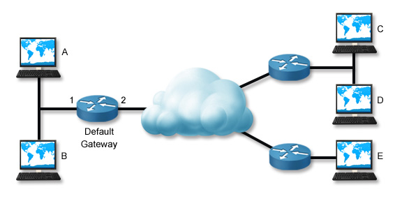
As part of the troubleshooting process, you need to identify the scope of the problem so you can take the proper actions to correct the problem.

In this scenario, Workstation A can't communicate with Workstation C.

Troubleshooting Process

The following table lists several tasks you can perform to troubleshoot the reported connectivity problem. These steps trace the problem backward from the remote host to the local host. Depending on the situation, you might be able to troubleshoot the problem more efficiently by skipping some tests or changing the order in which you perform them (you might even complete them in reverse order).

Task Description
Ping Host C Often, the best way to start troubleshooting a problem is to ping the host you are trying to contact. This verifies the reported problem. If the ping is successful, the problem is not related to network connectivity. Check other problems, such as name resolution or service access.
If you have access to another computer, try pinging the destination host from that computer. If the ping is successful, skip the remaining tasks and troubleshoot the local host configuration or physical connection.
Ping Host D If you cannot contact a specific remote host, try pinging another host in the same remote network. If the ping is successful, then the problem is with the remote host (for example, a misconfiguration, broken link, or unavailable host).
Ping Host E If you cannot contact any host in the remote network, try pinging hosts on other remote networks (you might try several other networks). If the pings are successful or if you can contact some remote networks and not others, then the problem is with the routing path between your network and the specific remote network. Use the traceroute/tracert commands to check the path to the problem network.
Ping the Default Gateway If you cannot contact any remote network, ping the default gateway router. If the ping is successful but you still cannot contact any remote host, have the router administrator verify the router configuration. Check for broken links to the remote network, interfaces that have been shut down, and access control lists or other controls that might be blocking traffic.
Ping Host B If you cannot contact the default gateway router, ping other hosts on the local network. If the pings are successful, check the default gateway router.
Troubleshoot the Local Host Connection or Configuration If you cannot communicate with any host on the local network, then the problem is likely with the local host or its connection to the network. Troubleshoot by doing the following:
  • Check physical connectivity
  • Validate the TCP/IP configuration on the local host
  • Validate IP configuration settings
You can use the route command on the router to view directly connected routes that have been set up. You can also use it on the default gateway of the local subnet and verify that the router has a route to the remote subnet. Another use of the route command is to view the routing table; this helps you see what networks the router knows about. In addition, the route command can be used to display additional networking information (not provided by ifconfig).

One special ping test you can perform is pinging the local host. By doing this, you are verifying that TCP/IP is correctly installed and configured on the local host. In essence, you are finding out if the workstation can communicate with itself. To ping the local host, use the following command:

ping 127.0.0.1

If this test fails, check to make sure TCP/IP is correctly configured on the system.

This test does not check physical connectivity. The ping can succeed even if the host is disconnected from the network.

ARP and netstat

The following table lists several commands that you can use on a Windows system to gather information about network connections.

Tool Option(s)
arp arp -a shows the IP address-to-MAC address mapping table (the address cache).
netstat netstat shows the active connections.
netstat -a shows detailed information for active connections.
netstat -r or route print shows the routing table of the local host.
netstat -s shows TCP/IP statistics.
arp table arp tables allow a system to build frames targeting remote MAC addresses.
Local computers have a cache of recently used IP addresses and their corresponding MAC addresses. When a computer needs to contact another computer on its own subnet, it first checks its cache for an entry of the IP address. If the entry is found, the corresponding MAC address is used to communicate with the destination computer. The cache can cause problems if the MAC address for a computer has recently changed (for example, if the network interface card has been replaced). To correct a problem, use the netsh command to clear the ARP cache.


arp -a shows the IP address-to-MAC address mapping table (the address cache).

A sample output looks like this:

```Interface: 192.168.1.141 on Interface 0x1000003 Internet Address Physical Address Type 192.168.1.1 00-40-10-18-7c-ed dynamic 192.168.1.20 00-0e-0c-4e-e0-b2 dynamic 192.168.1.21 00-0e-0c-4e-e1-fe dynamic 192.168.1.22 00-0e-0c-4e-df-c6 dynamic 192.168.1.23 00-d0-b7-b7-c2-af dynamic 192.168.1.26 00-0e-0c-4e-e9-d6 dynamic ``` </table>

Occasionally, the ARP table will have stale entries. This happens when:

  • The IP address assigned to a host changes (for example, if a DHCP server assigns it a different IP address).
  • The MAC address of a host changes (for example, if the NIC is replaced).

If this is the case, when the local computer consults its cache for ARP information, the information will be incorrect, and the computer will be unable to contact the remote host. To correct the problem, use the arp -d * command to delete the cache. This causes the computer to use ARP to rediscover the information.


netstat shows the active connections.

A sample output looks like this:

``` Active Connections Proto Local Address Foreign Address State TCP wrk1:microsoft-ds wrk1.westsim.local:1342 ESTABLISHED TCP wrk1:1342 wrk1.westsim.local:microsoft-ds ESTABLISHED TCP wrk1:1088 srv1.westsim.local:1026 ESTABLISHED TCP wrk1:1096 srv1.westsim.local:1865 ESTABLISHED TCP wrk1:1232 srv1.westsim.local:microsoft-ds ESTABLISHED ```

netstat -a shows detailed information for active connections.

A sample output looks like this:

``` Active Connections Proto Local Address Foreign Address State TCP wrk1:epmap wrk1.westsim.local:0 LISTENING TCP wrk1:microsoft-ds wrk1.westsim.local:0 LISTENING TCP wrk1:1039 wrk1.westsim.local:0 LISTENING TCP wrk1:1083 wrk1.westsim.local:0 LISTENING TCP wrk1:1088 wrk1.westsim.local:0 LISTENING TCP wrk1:1096 wrk1.westsim.local:0 LISTENING TCP wrk1:1232 wrk1.westsim.local:0 LISTENING TCP wrk1:netbios-ssn wrk1.westsim.local:0 LISTENING TCP wrk1:1088 srv1.westsim.local:1026 ESTABLISHED TCP wrk1:1096 srv1.westsim.local:1865 ESTABLISHED TCP wrk1:1232 srv1.westsim.local:microsoft-ds ESTABLISHED UDP wrk1:microsoft-ds *:* UDP wrk1:1027 *:* UDP wrk1:1044 *:* UDP wrk1:1091 *:* UDP wrk1:2967 *:* UDP wrk1:1305 *:* UDP wrk1:netbios-ns *:* UDP wrk1:netbios-dgm *:* UDP wrk1:isakmp *:* ```

netstat -r or route print shows the routing table of the local host.

A sample output looks like this:

``` Route Table =========================================================================== Interface List 0x1 ........................... MS TCP Loopback interface 0x1000003 ...00 06 5b 1c 92 b8 ...... 3Com EtherLink PCI =========================================================================== =========================================================================== Active Routes: Network Destination Netmask Gateway Interface Metric 0.0.0.0 0.0.0.0 192.168.1.1 192.168.1.141 1 127.0.0.0 255.0.0.0 127.0.0.1 127.0.0.1 1 192.168.1.0 255.255.255.0 192.168.1.141 192.168.1.141 1 192.168.1.141 255.255.255.255 127.0.0.1 127.0.0.1 1 192.168.1.255 255.255.255.255 192.168.1.141 192.168.1.141 1 224.0.0.0 224.0.0.0 192.168.1.141 192.168.1.141 1 255.255.255.255 255.255.255.255 192.168.1.141 192.168.1.141 1 Default Gateway: 192.168.1.1 =========================================================================== Persistent Routes: None ```

netstat -s shows TCP/IP statistics.

A sample output looks like this:

``` IP Statistics Packets Received = 81978 Received Header Errors = 0 Received Address Errors = 374 Datagrams Forwarded = 0 Unknown Protocols Received = 0 Received Packets Discarded = 0 Received Packets Delivered = 81776 Output Requests = 63048 Routing Discards = 0 Discarded Output Packets = 0 Output Packet No Route = 0 Reassembly Required = 0 Reassembly Successful = 0 Reassembly Failures = 0 Datagrams Successfully Fragmented = 0 Datagrams Failing Fragmentation = 0 Fragments Created = 0 ICMP Statistics Received Sent Messages 52 56 Errors 0 0 Destination Unreachable 3 0 Time Exceeded 0 0 Parameter Problems 0 0 Source Quenches 0 0 Redirects 0 0 Echos 0 56 Echo Replies 49 0 Timestamps 0 0 Timestamp Replies 0 0 Address Masks 0 0 Address Mask Replies 0 0 TCP Statistics Active Opens = 225 Passive Opens = 17 Failed Connection Attempts = 2 Reset Connections = 26 Current Connections = 3 Segments Received = 77862 Segments Sent = 62130 Segments Retransmitted = 0 UDP Statistics Datagrams Received = 3223 No Ports = 691 Receive Errors = 0 Datagrams Sent = 862 ```

arp -a shows the IP address-to-MAC address mapping table (the address cache).

A sample output looks like this:

``` Interface: 192.168.1.141 on Interface 0x1000003 Internet Address Physical Address Type 192.168.1.1 00-40-10-18-7c-ed dynamic 192.168.1.20 00-0e-0c-4e-e0-b2 dynamic 192.168.1.21 00-0e-0c-4e-e1-fe dynamic 192.168.1.22 00-0e-0c-4e-df-c6 dynamic 192.168.1.23 00-d0-b7-b7-c2-af dynamic 192.168.1.26 00-0e-0c-4e-e9-d6 dynamic ```

Occasionally, the ARP table will have stale entries. This happens when:

  • The IP address assigned to a host changes (for example, if a DHCP server assigns it a different IP address).
  • The MAC address of a host changes (for example, if the NIC is replaced).

If this is the case, when the local computer consults its cache for ARP information, the information will be incorrect, and the computer will be unable to contact the remote host. To correct the problem, use the arp -d * command to delete the cache. This causes the computer to use ARP to rediscover the information.

## tcpdump

TCPdump is a packet analyzer that runs in a command line utility. It allows the user to view TCP/IP and other packets as they are transmitted and received over on a computer's network. In this lesson, you will learn about:

  • Common uses
  • Options
  • Expression examples

Common Uses

TCPdump prints the contents of network packets. It can read packets from a network interface card or a previously captured packet file. TCPdump can write packets to standard output or a file.

You can TCPdump to intercept and display the network traffic of another user or computer, including user credentials, the content of packets, and other unencrypted information.

Options

These are some of the many configuration options for TCPdump. For a complete list of options refer to the TCPdump MAN (manual) page.

Option Description
-i any Listen on all interfaces to check for traffic traffic.
-i eth0 Listen on the eth0 interface.
-D Show the list of available interfaces.
-n Don't resolve host names.
-nn Don't resolve host names or port names.
-q Be less verbose (more quiet) with your output.
-t Create a timestamp output humans can read.
-tttt Create a timestamp output that's maximally readable for humans.
-X Show the packet's contents in both hex and ASCII.
-XX Same as -X, but also shows the Ethernet header.
-v, -vv, -vvv Increase the amount of packet information you get back.
-c Only receive a certain number of packets and then stop.
-s Define the snaplength (size) of the capture in bytes. Use -s0 to capture everything unless you are intentionally capturing less.
-S Print absolute sequence numbers.
-e Retrieve the Ethernet header.
-q Show less protocol information.
-E Decrypt IPsec traffic by providing an encryption key.

Expression Examples

Expressions allow you to filter traffic and find exactly what you need.

There are three main types of expression: type, dir, and proto.

  • The type options are host, net (the network address), and port.
  • Direction lets you insert the src (source) and dst (destination) commands.
  • Protocol lets you designate tcp, udp, icmp, ah, and many more options.

Some examples of uses for TCPdump include the following:

Commands are case sensitive.
TCPdump Example Description
tcpdump -D Display the list of interfaces TCPdump can listen to.
tcpdump -n host 192.168.0.1 Capture any packets that list 192.168.0.1 as the source or destination host. Displays IP addresses and port numbers.
tcpdump -i eth0 Listen on interface eth0.
tcpdump -i any Listen on any available interface.
tcpdump -n dst net 192.168.0.0/24 Capture any packets that list 192.168.0.0/24 as the destination network. Displays IP addresses and port numbers.
tcpdump -n src net 192.168.1.0/24 Capture any packets that list 192.168.1.0/24 as the source network. Displays IP addresses and port numbers.
tcpdump -n dst port 23 Capture any packets that list 23 as the destination port. Displays IP addresses and port numbers.
tcpdump -n "dst host 192.168.1.1 and (dst port 80 or dst port 443)" Capture any packets that list 192.168.0.1 as the destination IP and 80 or 443as the destination port. Displays IP addresses and port numbers.
## Troubleshooting Name Resolution

As you study this section, answer the following questions:

  • What are the symptoms of name resolution problems?
  • w
  • What is the difference between nslookup and dig?

In this section, you will learn to:

  • Use nslookup

The key terms for this section include:

Term Definition
tracert or traceroute The tracert or traceroute commands are used to show details about the path that a packet takes from the computer to whatever destination you specify.
nslookup A command-line tool used (in Windows and other operating systems) to query the Domain Name System (DNS) to obtain the domain name, the IP address mapping, or for any other specific DNS record.
dig Domain Information Groper (dig) is a Unix-like network administration command-line tool used to determine what a particular DNS server thinks the given host’s IP address should be.

Common name resolution problems include the following:

  • The DNS server could be down or otherwise unreachable.
  • There may be a routing problem between the sending host and the DNS server.
  • The sending host could be configured with the wrong IP address for the DNS server.

Name resolution problems typically have the following symptoms:

  • You can ping a destination host using its IP address, but not its host name.
  • Applications that use hostnames fail. This could include:
    • Entering a URL into a browser.
    • Pinging the host using the hostname.
    • Searching for the host by its name.

To troubleshoot DNS name resolution, use the following tools:

  • ping
  • tracert (Windows) or traceroute (Linux)
  • nslookup
  • dig (Linux)
  • host (Linux)

Troubleshoot DNS Name Resolution With Commands

The following table lists several ways to troubleshoot with commands:

Command Purpose Example
ping Contacts the DNS server to see if it responds. Be aware that the firewall protecting the DNS server may be configured to drop ICMP packets in order to prevent DoS attacks; if the server doesn't respond, it is not necessarily down.

ping 8.8.4.4

tracert or traceroute Tests the route between your workstation and the DNS server.

tracert 8.8.4.4

nslookup [host] Queries the IP address of a host.

nslookup www.mit.edu

nslookup Starts nslookup in interactive mode. The default interactive mode query is for A records, but you can use the set type= command to change the query type.

nslookup set type=ns

dig host name
host host name
Queries a host. The default query is for A records. You can change the default search by appending one of the record types below to the end of the command:
  • a—address records
  • any—any type of record
  • mx—mail exchange records
  • ns—name server records
  • soa—sort of authority records
  • hinfo—host info records
  • axfr—all records in the zone
  • txt—text records

dig www.vulture.com ns
host www.vulture.com -t ns

dig @IP address or host name domain Queries the root server at the IP address or host name for the domain's A records. You can change the default query type by appending a different record type to the end of the command.

dig @192.168.1.1 vulture.com ns

dig -x IP address
host IP address
Finds the host name for the queried IP address.

dig -x 62.34.4.72
host 62.34.4.72

Local computers have a cache of recently resolved DNS names. The cache holds the DNS name and its IP address. When you use a DNS name, the computer first checks its cache. If the name is in the cache, the corresponding IP address is used. This can cause problems if a host's IP address has changed. Old values in the cache might continue to be used temporarily, making communication via the DNS name impossible. To correct this problem on a Windows computer, run ipconfig /flushdns to delete the local DNS name cache.
</br> # Chapter 6 Switch Management ###### [Back to top](#Network-Security-and-Data-Communications)

As you study this section, answer the following questions:

  • What are the requirements for connecting a VTY (virtual terminal) to a Cisco device?
  • What types of cable can you use to connect a PC to a router console port?
  • What is the difference between a managed switch and an unmanaged switch?
  • What is the difference between in-band and out-of-band management?

In this section, you will learn to:

  • Use the command line interface (CLI).

The key terms for this section include:

Term Definition
Managed Switch A switch that must be configured before you can use it.
Unmanaged Switch An unmanaged switch allows Ethernet devices to communicate with one another automatically using auto-negotiation to determine parameters such as the data rate and whether to use half-duplex or full-duplex mode.
Out-of-Band Management Out-of-band management allows you to use a dedicated communication channel that separates management traffic from normal network traffic. Network switches and routers allow you to use console redirection to access the device's console through a built-in serial or USB port.

You must configure an enterprise network switch before you implement it. An unmanaged switch is a low-end switches available from many retail stores. To implement an unmanaged switch, plug it into a power outlet and connect your network devices with UTP cables. While unmanaged switches are convenient and easy to implement, they lack many of the advanced management and security features available. It is preferable to use a managed switch instead. A managed switch is a switch that must be configured before you can use it.

In-Band Management

In-band management allows you to perform router and switch management tasks using a standard network connection. You do this with management utilities your workstation operating system provides through a network connection. For example, tools such as Telnet and SSH provide in-band management. Using the same network connection for both data and management has several drawbacks:

  • You must compete with normal network traffic for bandwidth.
  • The network traffic created by the management utilities must have protection from sniffing attacks to ensure that hackers cannot capture sensitive configuration information.
  • If the network connection is unavailable or the device is unresponsive to network communications, you cannot perform management tasks.

Out-of-Band Management

Out-of-band management allows you to use a dedicated communication channel that separates management traffic from normal network traffic. Network switches and routers allow you to use console redirection to access the device's console through a built-in serial or USB port. For example, Cisco routers and switches do not use monitors, and you cannot connect a keyboard or a mouse directly to the device. Instead, you connect a standard PC to the device's console port to manage the device.

System Management

Use the following options to manage a Cisco device:

Cisco Connection Type Description
Console A console connection allows for a direct connection through a PC to the console port on the device. The PC needs a terminal emulation program (such as PuTTY) to connect to the device's command line interface. This is an example of out-of-band management. In the terminal emulation program, use the following settings:
  • 9600 baud (or a rate supported by your router)
  • Data bits = 8 (default)
  • Parity = None (default)
  • Stop bits = 1 (default)
  • Flow control = None
Virtual Terminal (VTY) A VTY connection connects through a LAN or WAN interface configured on the device. Use a program (such as PuTTY) to open the command line interface. This is an example of in-band management. The Cisco device must be configured with an IP address before a VTY connection can be made.
Security Device Manager (SDM) The Cisco SDM allows a web browser connection to the device using HTTPS. When connected, the SDM allows you to manage the security features and network connections through a web-based graphical user interface. This is an example of in-band management. Be aware of the following SDM settings:
  • 10.10.10.1 is the default IP address of the SDM.
  • The default value for both the username and password is cisco.
A new router may not be completely configured for an SDM connection, so you may need to make a console connection first.

Router and Switch Connection

Use the following cable types to make the initial connection to the switch or router for device management:

Cable Type Pin-outs Use

Rollover Ethernet Cable
1 ' 8
2 ' 7
3 ' 6
4 ' 5
5 ' 4
6 ' 3
7 ' 2
8 ' 1
Use a rollover Ethernet cable to connect the device's console port to the serial port on a PC. Connect the RJ45 end to the console port, and connect the serial end to the PC. A rollover cable is also called a console cable.
Many recently developed Cisco devices use a USB for the console connector, so you can access it with any standard USB cable.

Straight-Through Ethernet Cable
1 ' 1
2 ' 2
3 ' 3
6 ' 6
Use a straight-through Ethernet cable to connect an Ethernet port on a router to an Ethernet port on a hub or switch. You can then access the router from another PC connected to the same network using a VTY connection.
If the router has an AUI port, connect one end to an AUI transceiver before you connect to the router.

Crossover Ethernet Cable
1 ' 3
2 ' 6
3 ' 1
6 ' 2
Use a crossover Ethernet cable to connect an Ethernet port on a router directly to the NIC in a PC. Establish a VTY session from the PC to connect to the device.
If the router has an AUI port, connect one end to an AUI transceiver before you connect to the router.
## Switch IP Configuration

As you study this section, answer the following questions:

  • Why would you configure an IP address on a switch?
  • What does the ip address dhcp command allow you to do?

In this section, you will learn to:

  • Configure management VLAN settings.
  • Configure switch IP settings.

The key terms for this section include:

Term Definition
VLAN A VLAN (Virtual Local Network) is a group of devices on one or more local area networks (LANs) that are configured to communicate as if they were attached to the same wire when, in fact, they could be located on a number of different LAN segments.

Keep in mind the following facts about IP addresses configured on switches:

  • Basic switches operate at Layer 2, so they are able to perform switching functions with no IP address configured.
  • A switch does not need to have an IP address configured unless you want to manage it with an in-band management utility such as SSH or a web-based interface.
  • Switch ports do not have IP addresses unless the switch performs Layer 3 switching, which is not supported on all switches.
  • The switch itself only has one active IP address. The IP address identifies the switch as a host on the network.

Configure the Switch IP Address

To configure the switch IP address, set the address on the VLAN interface (a logical interface defined on the switch to allow management functions). By default, the VLAN is VLAN 1. Use the following commands to configure the switch IP address:

switch#config terminal

switch(config)#interface vlan 1

switch(config-if)#ip address IP_address subnet_mask

switch(config-if)#no shutdown

Enable Management From a Remote Network

To enable management from a remote network, configure the default gateway. Use the following command in global configuration mode:

switch(config)#ip default-gateway IP_address
You can use the ip address dhcp command to configure a switch (or a router) to get its IP address from a DHCP server. The DHCP server can be configured to deliver the default gateway and DNS server addresses to the Cisco device as well. A manually configured default gateway address overrides any address received from the DHCP server.
You can use the show cdp neighbors detail command to displays detailed information about neighboring devices including network address, enabled protocols, hold time, and software version.
## Switch Interface Configuration

As you study this section, answer the following questions:

  • How does the VLAN interface configuration mode differ from Ethernet, FastEthernet, and GigabitEthernet interface configuration modes?
  • What must you consider if you manually configure speed or duplex settings?
  • What happens when autonegotiation fails for the Ethernet interface on a Cisco device?
  • What is the default setting for all ports on a switch?

In this section, you will learn to:

  • Configure switch interfaces.
  • Configure switch ports.

The key terms for this section include:

Term Definition
Forwarding Database A forwarding database is a list of Layer 2 MAC addresses and the ports used to reach each device.
Content Addressable Memory
(CAM)
The Content Addressable Memory (CAM) table stores the relationship between the MAC addresses on the network and the switch port each one is connected to.
## Switch Forwarding

Bridges and switches build forwarding databases. A forwarding database is a list of Layer 2 MAC addresses and the ports used to reach each device. Bridges and switches automatically learn about devices to build the forwarding database, but a network administrator can also program the device database manually. When a frame arrives on a switch port (also called an interface), the switch examines the source and destination address in the frame header and uses the information to complete the following tasks:

Step Results

1. The switch examines the source MAC address of the frame and notes which switch port the frame arrived on.

If the source MAC address is:

  • Not in the switch's Content Addressable Memory (CAM) table, a new entry is added to the table that maps the source device's MAC address to the port on which the frame was received. Over time, the switch builds a map of the devices that are connected to specific switch ports.
  • Already mapped to the port on which the frame was received, no changes are made to the switch's CAM table.
  • Already in the switch's CAM table but the frame was received on a different switch port, the switch updates the record in the CAM table with the new port.

2. The switch examines the destination MAC address of the frame.

If the destination MAC address of the frame is:

  • A broadcast address, then the switch sends a copy of the frame to all connected devices on all ports. This is called flooding the frame.
  • A unicast address but no mapping exists in the CAM table for the destination address, the switch floods the frame to all ports. The connected device that the frame is addressed to will accept and process the frame. All other devices will drop the frame.
  • A unicast address and mapping exists in the CAM table for the destination address, the switch sends the frame to the switch port specified in the CAM table. This is called forwarding the frame.
  • A unicast address and mapping exists in the CAM table for the destination address, but the destination device is connected to the same port from which the frame was received, the switch ignores the frame and does not forward it. This is called filtering the frame.
## Switch Configuration Mode (Cisco)

The following image illustrates some of the configuration modes available on a Cisco switch:

Cisco Switch Configuration Modes

The following table describes some of these configuration modes:

</tr> </tbody></table> </div> ## Switch Configuration Commands List

The following table lists common switch configuration commands:

Mode Details CLI Mode Prompt
Interface Configuration

The switch has multiple interface modes depending on the physical (or logical) interface type. For this course, you should be familiar with the following switch interface modes:

  • Ethernet (10 Mbps Ethernet)
  • FastEthernet (100 Mbps Ethernet)
  • GigabitEthernet (1 GB Ethernet)
  • VLAN
The VLAN interface configuration mode is used to configure the switch IP address and for other management functions. It is a logical management interface configuration mode rather than the physical interface configuration modes used for the FastEthernet and GigabitEthernet ports.
Switch(config-if)#
Config-VLAN Config-VLAN mode:
  • Can perform all VLAN configuration tasks.
  • Applies changes immediately.
Do not confuse the Config-VLAN mode with the VLAN interface configuration mode.
Switch(config-vlan)#
VLAN Configuration VLAN configuration mode:
  • Allows you to configure a subset of VLAN features.
  • Does not apply changes until you save them, either before or while exiting the configuration mode.
  • Does not store changes in the regular switch configuration file.
For most modern Cisco switches, it is recommended that you configure VLAN parameters from config-vlan mode, as VLAN configuration mode is being deprecated (phased out).
</td/>
Switch(vlan)#
Line Configuration Use Line Configuration mode to configure parameters for the terminal line, such as the console, Telnet, and SSH lines. Switch(config-line)#
Command Action
switch(config)#interface FastEthernet 0/14

switch(config)#interface GigabitEthernet 0/1
Moves to interface configuration mode.
switch(config)#interface range fastethernet 0/14 - 24

switch(config)#interface range gigabitethernet 0/1 - 4

switch(config)#interface range fa 0/1 - 4 , 7 - 10

switch(config)#interface range fa 0/8 - 9 , gi 0/1 - 2
Moves to configuration mode for a range of interfaces.
switch(config-if)#speed 10

switch(config-if)#speed 100

switch(config-if)#speed 1000

switch(config-if)#speed auto
Sets the port speed on the interface.
switch(config-if)#duplex half

switch(config-if)#duplex full

switch(config-if)#duplex auto
Sets the duplex mode on the interface.
switch(config-if)#no shutdown

switch(config-if)#shutdown
Enables or disables the interface.
switch#show interface status Shows the interface status of all ports.
switch#show ip interface brief Shows the line and protocol status of all ports.

Switch Configuration Facts

Important facts about switch configuration include the following:

  • All switch ports are enabled (no shutdown) by default.
  • Port numbering on some switches begins at 1, not 0. For example, FastEthernet 0/1 is the first FastEthernet port on a switch.
  • Through auto-negotiation, the 10/100/1000 ports configure themselves to operate at the speed of attached devices. If the attached ports do not support auto-negotiation, you can explicitly set the speed and duplex parameters.
  • Some switches always use the store-and-forward switching method. On other models, you may be able to configure the switching method.
  • If the speed and duplex settings are set to auto, the switch  uses auto-MDIX to sense the cable type (crossover or straight-through) connected to the port and automatically adapts itself to the cable type used. When you manually configure the speed or duplex setting, it disables auto-MDIX, so you need to be sure you use the correct cable.
  • By default, the link speed and duplex configurations for Ethernet interfaces in Cisco devices are set using IEEE 802.3u auto-negotiation. The interface negotiates with remote devices to determine the correct settings. However, you can disable auto-negotiation con the Cisco device and other Ethernet network hosts and manually assign static values. Devices with auto-negotiation enabled try to negotiate link speed and duplexing, but get no response. When auto-negotiation fails, Cisco devices that have auto-negotiation enabled default to the following:
    • The interface attempts to sense the link speed. If it cannot, it uses the slowest link speed supported on the interface (usually 10 Mbps).
    • If the link speed selected is 10 Mbps or 100 Mbps, half-duplex is used. If it is 1000 Mbps, full-duplex is used.
## Virtual LANs

As you study this section, answer the following questions:

  • What are two advantages of creating VLANs on your network?
  • You have two VLANs configured on a single switch. How many broadcast domains are there? How many collision domains are there?
  • What happens if two devices on the same switch are assigned to different VLANs?

In this section, you will learn to:

  • Create VLANs.
  • Explore VLANs.

The key terms for this section include:

Term Definition
VLAN A VLAN (Virtual Local Network) is a group of devices on one or more local area networks (LAN) that are configured to communicate as if they were attached to the same wire when, in fact, they could be located on a number of different LAN segments.
VLAN ID Switches use VLAN identifications (IDs) to route VLAN traffic. VLAN IDs are appended to the header of each frame.
In addition, VLAN IDs allow switches to identify which VLAN the frame belongs to and are used for inter-switch traffic.
 

A virtual LAN (VLAN) uses switch ports to define a broadcast domain. When you define a VLAN, you assign devices on different switch ports to a separate logical (or virtual) LAN. Although a switch can support multiple VLANs, each switch port can only be assigned to one VLAN at a time. The following graphic shows a single-switch VLAN configuration:

In the single-switch VLAN configuration above, the following is true:

  • FastEthernet ports 0/1 and 0/2 are members of VLAN 1.
  • FastEthernet ports 0/3 and 0/4 are members of VLAN 2.
  • Workstations in VLAN 1 cannot communicate with workstations in VLAN 2 even though they are connected to the same physical switch. Communications between VLANs requires a router, just as with physical LANs.
  • Two broadcast domains are defined, each of which corresponds to one of the VLANs.
  • On Cisco switches, all ports are members of VLAN 1 by default.

VLAN IDs

Switches use VLAN IDs to route VLAN traffic. VLAN IDs:

  • Are appended to the header of each frame.
  • Allow switches to identify which VLAN the frame belongs to.
  • Are used for inter-switch traffic.
VLAN IDs are only understood by switches. VLAN IDs are added and removed by switches, not the clients.

VLAN Switch Benefits

VLANs with switches offer many administrative benefits. You can:

  • Create virtual LANs based on criteria other than physical location (such as workgroup, protocol, or service).
  • Simplify device moves (devices are moved to new VLANs by modifying the port assignment).
  • Control broadcast traffic and create collision domains based on logical criteria.
  • Control security (isolate traffic within a VLAN).
  • Load-balance network traffic (divide traffic logically rather than physically).
VLANs are commonly used with Voice over IP (VoIP) to separate voice traffic from data traffic. Traffic on the voice VLAN can be given a higher priority to ensure timely delivery.
## VLAN Commands List

To configure a simple VLAN, first create the VLAN, then assign ports to that VLAN. The following table shows common VLAN configuration commands:

Command Action
switch(config)#vlan [1-4094]

switch(config-vlan)#name [unique_name]
Defines a VLAN.
Gives the VLAN a name.
Naming the VLAN is optional. VLAN names must be unique.
switch(config)#no vlan [1-4094] Deletes a VLAN.
When you delete a VLAN, all ports assigned to the deleted VLAN remain associated with it and are, therefore, inactive. After a VLAN is deleted, you must reassign its ports to an appropriate VLAN.
switch(config-if)#switchport access vlan [1-4094] Assigns ports to the VLAN.
If you assign a port to a VLAN that does not exist, the VLAN is created automatically.
switch#show vlan

switch#show vlan brief
Shows a list of VLANs on the system.
switch#show vlan id [1-4064] Shows information for a specific VLAN.

Example

The following commands create VLAN 12, name it IS_VLAN, identify port 0/12 as having only workstations attached to it, and assign the port to VLAN 12.

switch#config t
switch(config)#vlan 12
switch(config-vlan)#name IS_VLAN
switch(config-vlan)#interface fast 0/12
switch(config-if)#switchport access vlan 12
## Trunking

As you study this section, answer the following questions:

  • What is trunking?
  • Why is trunking important to VLAN configuration?
  • What protocol does a Cisco switch use to automatically detect trunk ports?
  • By default, traffic from which VLANs are allowed on trunk ports?
  • What is the default configuration of most Cisco switches?

In this section, you will learn to:

  • Configure trunking
  • Configure the native VLAN
  • Configure allowed VLANs

The key terms for this section include:

Term Definition
VTP VLAN Trunking Protocol (VTP) is a Cisco proprietary protocol that propagates the definition of Virtual Local Area Networks (VLAN) on the whole local area network. Trunking occurs when you configure VLANs that span multiple switches.

Trunking occurs when you configure VLANs that span multiple switches, as shown in the following diagram:

In this example, each switch has two VLANs configured with one port on each VLAN. Workstations in VLAN 1 can only communicate with other workstations in VLAN 1. This means that workstations connected to the same switch in this example cannot communicate directly with each other. Communications between workstations within each VLAN must pass through the trunk link to the other switch.

Trunking Facts

Important facts regarding trunking and VLANs include the following:

  • Access ports are connected to endpoint devices (such as workstations), while trunk ports are connected to other switches.
  • An access port can be a member of only a single VLAN.
  • Trunk ports are members of all VLANs on the switch by default.
  • Any port on a switch can be configured as a trunk port.
  • By default, trunk ports carry traffic for all VLANs between switches. However, you can reconfigure a trunk port so that it carries only specific VLANs on the trunk link.

When trunking is used, frames that are sent over a trunk port are tagged with the VLAN ID number so the receiving switch knows which VLAN the frame belongs to. In VLAN tagging:

  • Tags are appended by the first switch in the path and removed by the last.
  • Only VLAN-capable devices understand the frame tag.
  • Tags must be removed before a frame is forwarded to a non-VLAN capable device.

A trunking protocol defines the process that switches use to tag frames with a VLAN ID. One widely implemented trunking protocol is the IEEE 802.1Q standard, which supports a wide range of switches from many device manufacturers. 802.1Q supports VLAN numbers 1 through 4094.

802.1Q trunking does not tag frames from the default VLAN, but does tag frames from all other VLANs. For example, suppose VLAN 1 is the default VLAN on a switch (the default setting on most Cisco switches). In this configuration, any frame on VLAN 1 that is placed on a trunk link is not assigned a VLAN tag. If a switch receives a frame on a trunk port that doesn't have a VLAN tag, the frame is automatically put on VLAN 1.

When using switches from multiple vendors in the same network, be sure that each device supports the 802.1Q standard.

The VLAN Trunking Protocol (VTP) simplifies VLAN configuration on a multi-switch network by propagating configuration changes between switches. For VTP to work, the switches must be connected by trunk links. With VTP, switches are configured in one of the following configuration modes:

  • A switch in server mode is used to modify the VLAN configuration. The switch then advertises VTP information to other switches in the network.
  • A switch in client mode receives changes from a VTP server switch and passes that information on to other switches. Changes cannot be made to the local VLAN configuration on a client switch.
  • A switch in transparent mode allows local configuration of VLAN information, but it does not update its configuration with information from other switches. Likewise, local VLAN information is not advertised to other switches. However, VTP information received on the network is passed on to other switches.

By default, most managed switches are preconfigured to operate in server mode. If you do not intend to use VTP, configure your switches to use transparent mode.

## Trunking Commands List

The following table lists important commands for configuring and monitoring trunking on a Cisco switch:

Command Action
Switch(config-if)#switchport mode trunk Enables trunking on the interface.
Switch(config-if)#switchport mode access Configures an interface as an access port, which disables trunking on the interface (if it was previously configured).
Switch(config-if)#switchport trunk encapsulation dot1q

Switch(config-if)#switchport trunk encapsulation negotiate

Sets the trunking protocol to 802.1Q.

Allows the trunking protocol to be negotiated between switches.

Switch(config-if)#switchport trunk native vlan [vlan_id] Configures the VLAN that sends and receives untagged traffic on the trunk port when the interface is in 802.1Q trunking mode.
Switch(config-if)#switchport trunk allowed vlan all

Switch(config-if)#switchport trunk allowed vlan add [vlan_id]
Defines which VLANs are allowed to communicate over the trunk.
Switch(config-if)#switchport trunk allowed vlan remove [vlan_id] Removes a VLAN from a trunk link.
Switch(config-if)#switchport access vlan [number] Assigns an interface to a VLAN.
Switch#show interface trunk

Switch#show interface fa0/1 trunk
Shows interface trunking information with the following:
  • Mode
  • Encapsulation
  • Trunking status
  • VLAN assignments

Example

Two distribution layer switches, SW1 and SW2, are connected through their respective Gi0/1 interfaces. The following commands configure a trunk link between the switches:

SW1>ena
SW1#conf t
SW1(config)#int gi 0/1
SW1(config-if)#switchport mode trunk
SW2>ena
SW2#conf t
SW2(config)#int gi 0/1
SW2(config-if)#switchport mode trunk
## Spanning Tree Protocol

As you study this section, answer the following questions:

  • Why does root switch selection never require a tie breaker?
  • When would you modify an STP mode?
  • How does PVST+ differ from Rapid PVST+?
  • How do ports work in a multiple VLAN environment?
  • How are root bridges designated in a multiple VLAN environment?
  • What happens during STP convergence?

In this section, you will learn to:

  • Configure STP
  • Select a root bridge
  • Configure Rapid PVST+
  • Find STP Info
  • Configure EtherChannels

The key terms for this section include:

Term Definition
Switching Loop Many networks implement redundant paths between multiple switches to create fault tolerance. However, providing redundant paths between segments could cause frames to pass between the redundant paths endlessly. This condition is known as a switching loop.
Spanning Tree Protocol
(STP)

The Spanning Tree Protocol (STP) is a network protocol that builds a loop-free logical topology for Ethernet networks.

Root Bridge The root bridge is the master bridge, or controlling bridge.
Designated Bridge A designated bridge is any other device that participates in forwarding packets through the network.
Backup Bridge All redundant devices are classified as backup bridges. They listen to network traffic and build the bridge database. However, they do not forward packets. They can take over if the root bridge or a designated bridge fails.

Many networks implement redundant paths between multiple switches to create fault tolerance. However, providing redundant paths between segments could cause frames to pass between the redundant paths endlessly. This condition is known as a switching loop.

To prevent switching loops, the IEEE 802.1d committee defined the Spanning Tree Protocol (STP). With STP, one switch for each route is assigned as the designated bridge. Only the designated bridge can forward packets. Redundant switches are assigned as backups.

The spanning tree protocol:

  • Eliminates loops.
  • Provides redundant paths between devices.
  • Enables dynamic role configuration.
  • Recovers automatically from a topology change or device failure.
  • Identifies the optimal path between any two network devices.

The spanning tree protocol uses a spanning tree algorithm (STA) to calculate the best loop-free path through a network by assigning a role to each bridge or switch. The bridge role determines how the device functions in relation to other devices and whether the device forwards traffic to other segments.

Bridge Role Types

The following table describes the three types of bridge roles:

Role Characteristics
Root bridge The root bridge is the master bridge, or controlling bridge.
  • There is only one root bridge in the network. The root bridge is the logical center of the spanning tree topology in a switched network.
  • The root bridge is determined by the switch with the lowest bridge ID (BID):
    • The bridge ID is composed of two parts—a bridge priority number and the MAC address assigned to the switch.
    • The default priority number for all switches is 32,768. This means the switch with the lowest MAC address becomes the root bridge unless you customize the priority values.
    • You can manually configure the priority number to force a specific switch to become the root switch.
  • The root bridge periodically broadcasts configuration messages. These messages are used to select routes and reconfigure the roles of other bridges if necessary.
  • All ports on a root bridge forward messages to the network.
Designated bridge A designated bridge is any other device that participates in forwarding packets through the network.
  • Designated bridges are selected automatically by exchanging bridge configuration packets.
  • To prevent bridge loops, there is only one designated bridge per segment.
Backup bridge All redundant devices are classified as backup bridges.
  • They listen to network traffic and build the bridge database. However, they will not forward packets.
  • They can take over if the root bridge or a designated bridge fails.

Port States

Devices send special packets called Bridge Protocol Data Units (BPDUs) out each port. BPDUs sent to and received from other bridges are used to determine bridge roles and port states, verify that neighbor devices are still functioning, and recover from network topology changes. During the negotiation process and normal operations, each switch port is in one of the following states:

Port State Description
Disabled A port in the disabled state is powered on but does not participate in forwarding or listening to network messages. A bridge must be manually placed in the disabled state.
Blocking When a device is first powered on, its ports are in the blocking state. Backup bridge ports are always in the blocking state. Ports in a blocking state receive packets and BPDUs sent to all bridges, but they will not process any other packets.
Listening The listening state is a transitory state between blocking and learning. The port remains in the listening state for a specific period of time. This time period allows network traffic to settle down after a change has occurred. For example, if a bridge goes down, all other bridges go into the listening state for a period of time. During this time, the bridges redefine their roles.
Learning A port in the learning state receives packets and builds the bridge database (associating MAC addresses with ports). A timer is also associated with this state. The port goes to the forwarding state after the timer expires.
Forwarding The root bridge and designated bridges are in the forwarding state when they can receive and forward packets. A port in the forwarding state can learn and forward. All ports of the root switch are in the forwarding state.

Port Types

During the configuration process, ports on each switch are configured as one of the following types:

Port Type Description
Root Port The port on a designated switch with the lowest port cost back to the root bridge is identified as the root port.
  • Each designated switch has a single root port (a single path back to the route bridge).
  • Root ports are in the forwarding state.
  • The root bridge does not have a root port.
Designated Port One port on each segment is identified as the designated port. The designated port identifies which port on the segment is allowed to send and receive frames.
  • All ports on the root bridge are designated ports (unless the switch port loops back to a port on the same switch).
  • Designated ports are selected based on the lowest path cost to get back to the root switch. Default IEEE port costs include the following:
    • 10 Mbps = 1000
    • 100 Mbps = 19
    • 1 Gbps = 4
    • 10 Gbps = 2
  • If two switches have the same cost, the switch with the lowest priority becomes the designated switch, and its port becomes the designated port.
  • If two ports have the same cost, the port on the switch with the lowest port ID becomes the designated port.
    • The port ID is derived from two numbers, the port priority and the port number.
    • The port priority ranges from 0–255, and its default setting is 128.
    • The port number is the number of the switch's port. For example, the port number for Fa0/3 is 3.
    • With the default port priority setting, the lowest port number becomes the designated port.
  • Designated ports are used to send frames back to the root bridge.
  • Designated ports are in the forwarding state.
Blocking Port A blocking port is any port that is not a root or a designated port. A blocking port is in blocking state.

Spanning Tree Configuration

Devices participating in the spanning tree protocol use the following process to configure themselves:

  1. At startup, switches send BPDUs out each port.
  2. Switches read the bridge ID contained in the BPDUs to elect (identify) a single root bridge (the device with the lowest bridge ID). All of the ports on the root bridge become designated ports.
  3. Each switch identifies its root port (the port with the lowest cost back to the root bridge).
  4. Switches on redundant paths identify a designated switch for each segment. A designated port is also identified on each designated switch.
  5. Remaining switch ports that are not root or designated ports are put in the blocking state to eliminate loops.
  6. After configuration, switches periodically send BPDUs to ensure connectivity and discover topology changes.

The following table lists commands used to configure spanning tree:

Command Function
Switch(config)#spanning-tree mode {pvst | rapid-pvst} Sets the spanning tree mode.
  • PVST+ (Per VLAN Spanning Tree Protocol), also known as PVSTP, is a Cisco proprietary protocol used on Cisco switches.
  • Rapid PVST+ is Cisco's proprietary version of Rapid STP, which is based on the 802.1w standard.
PVST+ and Rapid PVST+ are the same except that Rapid PVST+ uses a rapid convergence based on the 802.1w standard. To provide rapid convergence, Rapid PVST+ deletes learned MAC address entries on a per-port basis after receiving a topology change.
Switch(config)#spanning-tree vlan [1-4094] root primary Forces the switch to be the root of the spanning tree.
Switch(config)#spanning-tree vlan [1-4094] cost [1 - 200000000] Manually sets the cost. The cost range value depends on the path-cost calculation method:
  • Short method range: 1 - 65536.
  • Long method range: 1 - 200000000.
Switch(config)#spanning-tree vlan [1-4094] priority [0-61440] Manually sets the bridge priority number as follows:
  • The priority value ranges between 0 and 61440.
  • Each switch has the default priority of 32768.
  • Priority values are set in increments of 4096. If you enter another number, your value is rounded to the closest increment of 4096 or you are prompted to enter a valid value.
  • The switch with the lowest priority number becomes the root bridge.
Switch(config)#no spanning-tree vlan [1-4094] Disables spanning tree on the selected VLAN.
Switch#show spanning-tree Shows spanning tree configuration information, including the following:
  • Root bridge priority and MAC address
  • The cost to the root bridge
  • Local switch bridge ID and MAC address
  • The role and status of all local interfaces
  • The priority and number for each interface
To verify that spanning tree is working, look for an entry similar to the following for each VLAN:
Spanning tree enabled protocol ieee
Switch#show spanning-tree vlan [1-4094] root Shows information about the root bridge for a specific VLAN. Information shown includes:
  • The root bridge ID, including the priority number and the MAC address
  • The cost to the root bridge from the local switch
  • The local port that is the root port
Switch#show spanning-tree vlan [1-4094] bridge Shows spanning tree configuration information about the local switch for the specified VLAN. Information includes the local bridge ID, including the priority and MAC address.

Shortest Path Bridging Protocol

Even though STP is great at eliminating switching loops, it has a key weakness: it allows only a single active path between two switches at any given time. If that active link goes down, it can sometimes take 30 seconds or more for STP to detect that the link has gone down before it activates a redundant link. To address this weakness, a new protocol, Shortest Path Bridging (SPB), has been developed to eventually replace STP. SPB is a routing protocol defined in the IEEE 802.1aq standard that adds routing functions to Layer 2 switching. SPB uses a link-state routing protocol to allow switches to learn the shortest paths through a switched Ethernet network and dynamically adjust those paths as the topology changes, just like a Layer 3 router does.

SPB addresses this issue by applying Layer 3 routing protocols to Layer 2 switches. This allows those switches to actually route Ethernet frames between switches, just as Layer 3 protocols route packets between routers. By doing this, SPB allows multiple links between switches to be active at the same time without creating a switching loop. This functionality is designed to eliminate the time lag associated with failed links managed by STP. If a link between switches goes down on a network that uses SPB, the frames can be immediately re-routed to the destination segment by using redundant links between switches that are already active and able to forward frames.

## EtherChannel

EtherChannel combines multiple ports on a Cisco switch into a single logical link between two switches. With EtherChannel:

  • You can combine 2–8 ports into a single link.
  • All links in the channel group are used for communication between the switches.
  • Bandwidth between switches is increased.
  • Automatic redundant paths between switches are established. If one link fails, communication will still occur over the other links in the group.
  • Spanning tree convergence times are reduced.


EtherChannel Configuration Protocols

Cisco switches can use the following protocols for EtherChannel configuration:

Protocol Description
Port Aggregation Protocol (PAgP) Port Aggregation Protocol prevents loops, limits packet loss due to misconfigured channels, and aids in network reliability. PAgP operates in the following modes:
  • Auto mode places the port into a passive negotiating state and forms an EtherChannel if the port receives PAgP packets. While in this mode, the port does not initiate the negotiation.
  • Desirable mode places the port in a negotiating state to form an EtherChannel by sending PAgP packets. A channel is formed with another port group in either the auto or desirable mode.
Link Aggregation Control Protocol (LACP) Link Aggregation Control Protocol is based on the 802.3ad standard and has similar functions to PAgP. LACP is used when configuring EtherChannel between Cisco switches and non-Cisco switches that support 802.3ad. LACP operates in the following modes:
  • Passive mode places the port into a passive negotiating state and forms an EtherChannel if the port receives LACP packets. While in this mode, the port does not initiate the negotiation.
  • Active mode places the port in a negotiating state to form an EtherChannel by sending LACP packets. A channel is formed with another port group in either the active or passive mode.


EtherChannel Configuration Commands

The following table shows common commands that configure EtherChannel:

Command Action
Switch(config-if)#channel-protocol lacp

Switch(config-if)#channel-protocol pagp
Selects the EtherChannel protocol on the interface.
Switch(config-if)#channel-group [1-8] mode auto

Switch(config-if)#channel-group [1-8] mode desirable
Selects the PAgP mode on the interface.
Switch(config-if)#channel-group [1-8] mode active

Switch(config-if)#channel-group [1-8] mode passive
Selects the LACP mode on the interface.
Switch(config-if)#no channel-group [1-8] Disables EtherChannel on the interface.
Switch#show etherchannel Displays EtherChannel details on the switch.
Switch#show etherchannel summary Displays EtherChannel information for a channel with a one-line summary per channel group.
Each channel group has its own number. All ports assigned to the same channel group are viewed as a single logical link.

Examples

The following commands configure GigabitEthernet 0/1 and 0/2 interfaces to actively initiate the negotiation of an EtherChannel with the PAgP protocol and a channel group of 5:

Switch>ena
Switch#conf t
Switch(config)#int range gi 0/1 - 2
Switch(config-if-range)#channel-protocol pagp
Switch(config-if-range)#channel-group 5 mode desirable

The following commands configure FastEthernet 0/1 through 0/4 interfaces to form an EtherChannel with the LACP protocol if the other device actively initiates the EtherChannel connection:

Switch>ena
Switch#conf t
Switch(config)#int range ga 0/1 - 4
Switch(config-if-range)#channel-protocol lacp
Switch(config-if-range)#channel-group 3 mode passive
Switch(config-if-range)#duplex full


Troubleshoot EtherChannel Configuration

Use the following guidelines to troubleshoot an EtherChannel configuration:

  • Make sure that all ports in an EtherChannel use the same protocol (PAgP or LACP):
    • If the channel-group command is used with the desirable option on one switch (PAgP), the other switch must use either desirable or auto.
    • If the channel-group command is used with the active option (LACP), the other switch must use either active or passive.
  • Verify that all ports in the EtherChannel have the same speed and duplex mode. LACP requires that the ports operate only in full-duplex mode.
  • Check the channel group number. A port cannot belong to more than one channel group at the same time.
  • Verify that all ports in the EtherChannel have the same access VLAN configuration or are VLAN trunks with the same allowable VLAN list and the same native VLAN.
  • Check the spanning tree configuration. If you do not configure EtherChannel, the spanning tree algorithm identifies each link as a redundant path to the other bridge and puts one of the ports in a blocking state.
  • Check the port type and number. You can configure an LACP EtherChannel with up to 16 Ethernet ports of the same type. Up to eight ports can be active, and up to eight ports can be in standby mode.
  • Be sure to enable all ports in an EtherChannel. A port in an EtherChannel that is disabled using the shutdown interface configuration command is treated as a link failure, and its traffic is transferred to one of the remaining ports in the EtherChannel.
Do not configure more than six EtherChannels on one switch.
## Switch Troubleshooting

As you study this section, answer the following questions:

  • You have a network connected by switches with a single device connected to each switch port. Why would you be surprised to see collisions on this network?
  • What is a duplex mismatch?
  • What conditions lead to a broadcast storm?
  • How can you prevent switching loops from forming?
  • You moved a device from one switch port to another, and now it cannot communicate with any other device on the network. The switch link lights are lit. What switch configuration should you check?
  • Other than the switch configuration, what should you check if you see excessive frame errors on the switch?

The key terms for this section include:

Term Definition
Broadcast Storm A broadcast storm is excessive broadcast traffic that renders normal network communications impossible.
Collisions A collision occurs when two devices that share the same media segment transmit at the same time.
Duplex Mismatch A duplex mismatch occurs when two devices use different duplex settings. For example, when one device tries to transmit using full duplex while the other expects half duplex communications.
Frame Errors The switch examines incoming frames and only forwards frames that are complete and correctly formed; invalid frames are simply dropped. These types of frames are known as frame errors.

The following table lists several problems you might encounter when managing switches on your network:

Issue Description
Bad Port A bad port is a faulty or bad interface on a switch. To fix the problem, you need to return the switch back to the supplier and get a replacement. However, if you have plenty of ports on the switch, you can configure the port using 'description ** Bad Port **', and then insert a RJ45 single connector into the bad port to occupy the port.
Broadcast Storm A broadcast storm is excessive broadcast traffic that renders normal network communications impossible. The following can cause broadcast storms:
  • Switching loops that cause broadcast traffic to circulate endlessly between switches
  • Denial of Service (DoS) attacks
To reduce broadcast storms, complete the following:
  • Run STP to prevent switching loops.
  • Implement switches with built-in broadcast storm detection, which limits the bandwidth that broadcast traffic can use.
  • Use VLANs to create separate broadcast domains on switches.
Collisions A collision occurs when two devices that share the same media segment transmit at the same time. In a switched network, collisions should only occur on ports that have more than one device attached (such as a hub with workstations connected to it).
  • To eliminate collisions, connect only a single device to each switch port. For example, if a hub is connected to a switch port, replace it with another switch.
  • If collisions are still detected, troubleshoot cable and NIC issues.
Duplex Mismatch A duplex mismatch occurs when two devices use different duplex settings. In this case, one device tries to transmit using full duplex, while the other expects half duplex communications. By default, devices are configured to use auto-negotiation to detect the correct duplex setting to use. If a duplex method cannot be agreed upon, devices default to half duplex.

A duplex mismatch can occur in the following cases:

  • Both devices are configured to use different duplex settings.
  • Auto-negotiation does not work correctly on one device.
  • One device is configured for auto-negotiation, and the other device is manually configured for full duplex.
Symptoms of a duplex mismatch include very slow network communications. Ping tests might appear to complete correctly, but normal communications work well below the expected speeds, even for half duplex communications.
Frame Errors The switch examines incoming frames and only forwards frames that are complete and correctly formed; invalid frames are simply dropped. Most switches include logging capabilities to track the number of corrupt or malformed frames. The following are common causes of frame errors:
  • Frames that are too long are typically caused by a faulty network card that jabbers (constantly sends garbage data).
  • Frames that are too short are typically caused by collisions.
  • CRC errors indicate that a frame has been corrupted in transit.
  • All types of frame errors can be caused by faulty cables or physical layer devices.
Incorrect VLAN Membership VLANs create logical groupings of computers based on switch port. Because devices on one VLAN cannot communicate directly with devices in other VLANs, incorrectly assigning a port to a VLAN can prevent a device from communicating through the switch.
With VLAN membership, static port assignment is defined by switch port, not by a MAC address. Connecting a device to a different switch port could change the VLAN membership of the device. On the switch, verify that ports are assigned to the correct VLANs and that any unused VLANs are removed from the switch.
Slow Link Speed Most network components are capable of supporting multiple network specifications. By default, these devices use the maximum speed supported by all devices on the network.

If the speed of a segment is lower than expected (for example, 10 Mbps instead of 100 Mbps, or 100 Mbps instead of 1000 Mbps), complete the following:

  • Check individual devices to verify that they all support the higher speed.
  • Check individual devices to see if any are manually configured to use the lower speed.
  • Use a cable certifier to verify that the cables meet the rated speeds. Bad cables are often the cause of 1000BaseT networks operating at only 100BaseTX speeds.

# Chapter 7 Routing ###### [Back to top](#Network-Security-and-Data-Communications)
Term Definition
Packet A packet is the payload of an OSI Layer 2 frame. A packet has a header and a payload. The header contains the source and destination IP addresses. The payload depends on the protocol that formed the packet.
Network When used in routing, the term network can be defined as a broadcast domain where all the hosts have the same network portion in their IP address. Normally, a LAN fits this more precise definition of a network.
Routing Table The routing table is a database of entries containing:
  • The address of a known network.
  • The next hop gateway (router).
  • The network interface to reach the next hop gateway.
  • A metric or cost that indicates the desirability of the route (Tte lower the metric, the more desirable the route).
Next Hop An IP address entry in a router's routing table that specifies the next or closest router in its routing path.
Default Route The default route is an entry of 0.0.0.0 in a routing table. This entry matches every network.
Loopback Entry Loopback entries contains loopback addresses, which are used for diagnostics and for troubleshooting the TCP/IP stack.

Routing is the process of moving packet from one network to another using routers. In this lesson you will learn about:

  • How routing works
  • Static and dynamic routing
  • Interior and exterior routing

How Routing Works

A router is a device that sends packets from one network to another.

Term Description
Packet A packet is the payload of an OSI layer 2 frame. A packet has a header and a payload.
  • The header contains source and destination IP addresses.
  • The payload depends on the protocol that formed the packet.
Network When used in routing, the term network can be defined as a broadcast domain where all the hosts have the same network portion in their IP address. Normally, a LAN fits this more precise definition of a network.

To perform routing, a router:

  • Receives a frame
  • Opens the frame's payload, which is an IP packet
  • Reads the packet header to find IP addressing information
  • Matches the destination network address with entries in its routing table creates a new frame using the packet as a payload
  • Transmits the new frame to the next hop gateway.

The following table describes a few important routing terms:

Term Description
Next Hop To forward a packet, a router only needs to know next hop information, not the full path to the ultimate destination. The next hop is the gateway (router) that the router will to send the packet to.
Routing Table The routing table is a database of entries, each with:
  • The address of a known network
  • The next hop gateway (router)
  • The network interface to reach the next hop gateway
  • A metric or cost that indicates the desirability of the route (The lower the metric, the more desirable the route.)
Default Route The default route is an entry of 0.0.0.0 in a routing table. This entry matches every network. If no other entry in the routing table matches the destination IP address in a packet, the router will send the packet to the gateway found in the default route.
  • The gateway identified in the default route is known as the default gateway.
  • If a default route does not exist, the router will drop any packets that do not match an entry in a routing table.
Loopback Entry Loopback entries contains loopback addresses which are used for diagnostics and for troubleshooting the TCP/IP stack. Loopback interfaces are always available. They will continue to run even if other physical interfaces in the router are down.

Static and Dynamic Routing

Routing can be classified by how entries are added to the routing table. There are three types of routing entries—default, static and dynamic. You can use default, static and dynamic routing together.

Information about other networks can be added to the routing table using one of two methods:

Method Description
Static Static routing entries are manually added to the routing table.
  • A route entry of 0.0.0.0 identifies the default entry or default route which is special form of a static entry.
  • Static entries remain in the routing table until they manually removed.
  • When changes to the network occur, static entries must be modified, added, or removed.
  • Static routing works well in smaller networks.
Dynamic Maintaining static only routing in a large network with multiple routers would be very difficult, especially when there are multiple network paths that an IP packet can take to get to its destination. Routers can dynamically learn about networks by sharing routing information with other routers.
  • Dynamic routing is implemented by enabling a routing protocol.
  • A routing protocol adds dynamic entries to the routing table.
  • If multiple paths to a network are available, routing protocols define:
    • The algorithm used to calculate a metric.
    • How routers communicate with each other to share network path information.
  • Routing protocols use metric information to insert the best hop into the routing table when multiple paths are available.

If needed, you can add static routes to supplement dynamic routing to identify networks that are not learned about through any routing protocol.

Interior and Exterior Routing

Dynamic routing protocols can be classified by their use, either for interior routing or exterior routing.

Routing Use Description
Interior Interior routing is done within an autonomous system (AS). An autonomous system is a private network that is somewhat independent of the internet. The only thing that is shared is the link to the internet.

With interior routers:

  • You own and control the routers.
  • You determine where the routers are located.
    • You control the logical topology.
    • You control the physical topology.
  • You control the interfaces that connect the routers to your network.
  • You determine which interior routing protocols are enabled.
Exterior Exterior routing is done between autonomous systems. Organizations that connect their private network to the internet are assigned a unique autonomous system number, or ASN.
  • Exterior routing is the routing performed by the so-called internet backbone.
  • In most organizations, exterior routing will be limited to a single router that connects the organizations network to the internet via an ISP.
    • This router is often called a border router or an edge router.
  • Larger organizations or organizations with a critical mission may have multiple ISPs that give them redundant internet connectivity. In this case, the edge router or routers must run an exterior routing protocol.
| Protocol | Type | Category | Description | | -------------------------------------------------- | ---- | --------------- | ---| | Routing Information Protocol (RIP) | IGP | Distance Vector | RIP is a distance vector routing protocol used for routing within an autonomous system (such as an IGP). RIP uses hop count as the metric. RIP network size is limited to a maximum of 15 hops between any two networks. A network with a hop count of 16 indicates an unreachable network. RIP v1 is a classful protocol; RIP v2 is a classless protocol. RIP is best suited for small private networks. | | Enhanced Interior Gateway Routing Protocol (EIGRP) | IGP | Hybrid | EIGRP is a hybrid routing protocol developed by Cisco for routing within an AS. EIGRP uses a composite number for the metric, which indicates bandwidth and delay for a link. The higher the bandwidth, the lower the metric. EIGRP is a classless protocol. EIGRP is best suited for medium to large private networks. | | Open Shortest Path First (OSPF) | IGP | Link State | OSPF is a link state routing protocol used for routing within an AS. OSPF uses relative link cost for the metric. OSPF is a classless protocol. OSPF divides a large network into areas. Each autonomous system requires an area 0 that identifies the network backbone. All areas are connected to area 0, either directly or indirectly through another area. Routes between areas must pass through area 0. Internal routers share routes within an area; area border routers share routes between areas; autonomous system boundary routers share routes outside of the AS. A router is the boundary between one area and another area. OSPF is best suited for large private networks. | | Intermediate System to Intermediate System (IS-IS) | IGP | Link State | IS-IS is a link-state routing protocol used for routing within an AS. IS-IS uses relative link cost for the metric. IS-IS is a classless protocol. The original IS-IS protocol was not used for routing IP packets; use integrated IS-IS to include IP routing support. IS-IS divides a large network into areas. There is no area 0 requirement, and IS-IS provides greater flexibility for creating and connecting areas than OSPF . L1 routers share routes within an area. L2 routers share routes between areas. An L1/L2 router can share routes with both L1 and L2 routers. A network link is the boundary between one area and another area. IS-IS is best suited for large private networks; it supports larger networks than OSPF. IS-IS is typically used within an ISP and easily supports IPv6 routing. | | Border Gateway Protocol (BGP) | EGP | Hybrid | BGP is an advanced distance vector protocol (also called a path vector protocol). BGP is an exterior gateway protocol (EGP) used for routing between autonomous systems. BGP uses paths, rules, and policies instead of a metric for making routing decisions. BGP is a classless protocol. Internal BGP (iBGP) is used within an autonomous system; External BGP (eBGP) is used between autonomous systems. BGP is the protocol used on the internet; ISPs use BGP to identify routes between autonomous systems. Very large networks can use BGP internally, but typically share routes on the internet only if the AS has two (or more) connections to the internet through different ISPs. |

As you study this section, answer the following questions:

  • What network link characteristics are used by routing protocols when computing a metric value or cost?
  • How does a distance vector routing protocol differ from a link state routing protocol?
  • How are routing paths shared by distance vector routing protocols?
  • How are routing paths shared by link state routing protocols?
  • What is a hybrid routing protocol?
  • How is administrative distance used to select a best path?
  • What is the difference between RIP and RIPv2? Why is this important in today's networks?
  • Which routing protocol is typically used within an ISP? Which protocol is used on the internet?
  • Which routing protocols divide an autonomous system into areas?
  • How does IS-IS differ from OSPF?

In this section, you will learn to:

  • Configure a router with static routes.
  • Enable OSPF routing.

The key terms for this section include:

Term Definition
Hop Count The distance between networks can be measured in hop counts, or the number times a router forwards an IP packet from one network to another. For a directly connected link, the hop count is zero.
Bandwidth Network bandwidth measures the capacity of a link. If bandwidth is a factor in the cost, a link with a lower capacity link will have a higher cost than a link with high bandwidth.
Throughput Although the advertised bandwidth is the maximum capacity of a link, its actual throughput will be less due to latency and other network overhead. If used in the cost calculation, larger throughput will contribute to a lower cost.
Link Utilization Link utilization is the percentage of a network's bandwidth that is currently being consumed by network traffic. If utilization is used, the cost will be less for links with low utilization.
Load The load on a router refers to the amount of computational work that it performs. If load is a factor in the cost, links for routers that are performing under heavy load will have a higher cost.
MTU The maximum transmission unit (MTU) setting on a router determines the maximum payload size for a frame. While this characteristic is not usually included in a metric, it is sometimes used as a tie-breaker when two links or paths have the same cost.
Packet Loss Packet loss occurs when IP packets fail to reach their destination. If it is used in calculating cost, a link that experiences greater packet loss will have a higher cost.
Latency Latency is the delay in transmissions over the path. If latency is used in the cost, a path with higher latency has a higher cost.
Reliability Reliability is measured by how often the path is down. If it is used in cost calculations, a highly reliable path has a lower cost.

Routers use a routing protocol to assign a metric to a network path and exchange information about paths with other routers. In this lesson, you will learn about:

  • Routing metrics
  • Routing protocol categories
  • Distance vector protocols
  • Link state protocols
  • Hybrid protocols
  • Administrative distance
  • Configure a static route

Routing Metrics

If there are multiple paths to a distant network, a routing protocol will assign a metric to each directly connected network link. The metric value can be thought of as the cost of sending a packet over that link. The metric is used when determining the best path to a network.

A routing protocol can use one or more of the following characteristics:

Characteristic Description
Hop Count The distance between networks can be measured in hop counts, or the number times a router forwards an IP packet from one network to another. For a directly connected link, the hop count will be zero.
Bandwidth Network bandwidth measures the capacity of a link. If bandwidth is a factor in the cost, a link with a lower capacity link will have a higher cost than a link with a high bandwidth link.
Throughput Although the advertised bandwidth is the maximum capacity of a link, its actual throughput will be less due to latency and other network overhead. If used in the cost calculation, larger throughput will contribute to a lower cost.
Link Utilization Link utilization is the percentage of a network's bandwidth that is currently being consumed by network traffic. If utilization is used, the cost will be less for links with low utilization.
Load The load on a router refers to the amount of computational work that it performs. If load is a factor in the cost, links for routers that are performing under heavy load will have a higher cost.
MTU The maximum transmission unit (MTU) setting on a router determines the maximum payload size for a frame. While this characteristic is not usually included in a metric, it is sometimes used as a tie-breaker when two links or paths have the same cost.
Packet Loss Packet loss occurs when IP packets fail to reach their destination. If it is used in calculating cost, a link that experiences greater packet loss will have a higher cost.
Latency Latency is the delay in transmissions over the path. If latency is used in the cost, a path with higher latency will have a higher cost.
Reliability Reliability is measured by how often the path is down. If it is used in cost calculations, a highly reliable path will have a lower cost.

Routing Protocol Categories

There are two primary categories of gateway protocols, distance vector protocols and link state protocols. A third category is a combination of these two, hybrid protocols. There is only one popular exterior routing protocol, and it is a hybrid protocol.

The difference in these categories of routing protocols is:

  • How metric values are calculated
  • How path information is shared between routers

Distance Vector Routing Protocols

Distance vector routing protocols:

  • Set a metric value or cost based on how far away a network is.
    • Are generally measured by hop count.
    • May measure distance by delay, packets lost, or something similar.
  • Set a direction that is associated with the distance.
    • Direction refers to the network interface that is used to forward the IP packet to the distant network.

When using a distance vector protocol, a router:

  • Will only share information with its direct neighbors (the next hop routers).
  • Will share all route information that it knows about.
    • Directly connected routes
    • Routes learned from its direct neighbors
  • Will send route information at a regularly scheduled time.

Convergence occurs when all routers share a consistent view of the network. Each router will used converged path information to insert next hop information for each learned path into the routing table. It does this by choosing the route with the lowest metric.

Link State Routing Protocols

  1. Link state protocols are also known as shortest path first protocols. The following is the general process employed by a router that uses link state protocols for finding best hop information.
  2. The router examines its directly connected network links and assigns a metric value.
    • The metric value is based on the status and connection type of the link.
    • The metric value may also include other factors, such as bandwidth and delay.
  3. The router determines the neighbor routers that are connected by each direct network link.
  4. The router builds a link-state packet (LSP) that contains a list of its neighbors and the metric value of the link to that neighbor.
  5. Through a process called flooding, the router sends the LSP to its neighbor routers.
  6. Neighboring routers, in turn, sends the LSP to its neighbors, and so on.
    • To eliminate looping, each router forwards the packet to every neighbor except the one it received the packet from.
    • A smart flooding algorithm prevents looping when there are circular routing paths.
  7. Using converged route information, the router constructs a complete map of the routing topology.
  8. From this map, the router will calculate the best path to each destination network.
    • Best path is determined using Dijkstras’s algorithm, which calculates the shortest path first.
  9. Using the link-state protocol, the router uses the best path information to insert next hop information for each network path into the routing table.

Administrative Distance

When more than one protocol is enabled on a router, each protocol is given an administrative distance. When the best path is being determined, protocols with a lower administrative distance are chosen over those with a higher administrative distance.

Most routers have a default administrative distance assigned to each routing protocol.

Source of the Route Default Administrative Distance
Connected interface or static route to an interface 0
Static route to an IP address 1
EIGRP summary 5
BGP external 20
EIGRP internal 90
IGRP 100
OSPF 110
IS-IS 115
RIP 120
EIGRP external 170
BGP internal 200
Unknown source 255

Configure a Static Route

To configure a static route, enter the following commands at the prompt:

SFO>enable
SFO#configure terminal
SFO(config)#ip route network_address subnet gateway
SFO(config)#ip route 0.0.0.0 0.0.0.0 gateway
SFO(config)#exit
SFO#copy run start

## Routing config Lab solutions:

Enter the following commands to configure the SFO static routes:

  1. In the diagram, select the SFO router.
  2. Press Enter.
  3. At the prompt, enter:

    SFO>enable
    SFO#configure terminal
    SFO(config)#ip route 10.0.0.0 255.0.0.0 172.17.12.98
    SFO(config)#ip route 0.0.0.0 0.0.0.0 160.12.99.1

    Make sure to add a space between the 2 octets of zeros.

    SFO(config)#exit
    SFO#copy run start

  4. Press Enter.
  5. Press Enter to save your changes.
Explanation

In this lab, your task is to complete the following:

  • Configure the Salta router to share information about all directly connected routes with the Jujuy router.
  • When you are finished, save your changes.

When configuring OSPF, routers do not need to use the same process ID, but networks must be defined in the same area. When adding network statements, include the wildcard mask and the area number (in this case, area 0).

Complete this lab as follows:

  1. Select Salta.
  2. Press Enter.
  3. At the prompt, enter:
    Salta>enable
    Salta#config t
    Salta(config)#router ospf 100
    Salta(config-router)#network 192.168.1.0 0.0.0.255 area 0
    Salta(config-router)#network 192.168.2.0 0.0.0.255 area 0
    Salta(config-router)#network 172.17.150.140 0.0.0.3 area 0
  4. Press Ctrl + Z.
  5. Enter the following command at the prompt:
    Salta#copy running-config startup-config
  6. Press Enter.
  7. Press Enter to save your changes.

NAT

| Term |Definition | | ---- | ---- | | Network Address Translation (NAT) | NAT translates private addresses to the public address of the NAT router. This allows you to connect a private network to the internet without obtaining registered (public) addresses for every host. | | Port Address Translation (PAT) | Technically speaking, NAT translates one address to another. Port address translation (PAT) associates a port number with the translated address. |

Network address translation (NAT) allows you to connect a private network to the internet without obtaining registered addresses for every host. This lesson covers:

  • How NAT works
  • Implementing NAT
  • Reserved private IP addresses

How NAT Works

NAT works by translating private addresses to the public address of the NAT router.

  • Hosts on the private network share the IP address of the NAT router or a pool of addresses assigned for the network.
  • The NAT router maps port numbers to private IP addresses. Responses to internet requests include the port number appended by the NAT router. This allows the NAT router to forward responses back to the correct private host.
  • Technically speaking, NAT translates one address to another. Port address translation (PAT) associates a port number with the translated address.
    • With only NAT, you would need a public address for each private host. NAT associates a single public address with a single private address.
    • PAT allows multiple private hosts to share a single public address. Each private host is associated with a unique port number on the NAT router.
    • Because virtually all NAT routers perform PAT, you normally use PAT, and not just NAT, when you use a NAT router. (NAT is usually synonymous with PAT.)

Implementing NAT

When you implement NAT, be aware of the following:

  • NAT supports a limit of 5,000 concurrent connections.
  • NAT provides some security for the private network because it translates or hides private addresses.
  • A NAT router can act as a limited-function DHCP server, assigning addresses to private hosts.
  • A NAT router can forward DNS requests to the internet.

The following table describes three types of NAT implementation.

| Type | Description | | --- | --- | | **Dynamic NAT** | Dynamic NAT automatically maps internal IP addresses with a dynamic port assignment. On the NAT device, the internal device is identified by the public IP address and the dynamic port number. Dynamic NAT allows internal (private) hosts to contact external (public) hosts, but not vice versa—external hosts cannot initiate communications with internal hosts. This implementation is also sometimes called many-to-one NAT because many internal private IP address are mapped to one public IP address on the NAT router. | | **Static NAT (SNAT)** | Static NAT maps a single private IP address to a single public IP address on the NAT router. Static NAT is used to take a server on the private network (such as a web server) and make it available on the internet. Using a static mapping allows external hosts to contact internal hosts—external hosts contact the internal server using the public IP address and the static port. This implementation is called one-to-one NAT because one private IP address is mapped to one public IP address. In addition to static NAT, the term SNAT also means source NAT, stateful NAT, and secure NAT. Although the terms vary, the function is the same. One commonly used implementation of static NAT is called port forwarding. Port forwarding allows incoming traffic addressed to a specific port to move through the firewall and be transparently forwarded to a specific host on the private network. Inbound requests are addressed to the port used by the internal service on the router's public IP address (such as port 80 for a web server). This is often called the public port. Port forwarding associates the inbound port number with the IP address and port of a host on the private network. This port is often called the private port. Based on the public port number, incoming traffic is redirected to the private IP address and port of the destination host on the internal network. Port forwarding is also called destination network address translation, or DNAT. | | **Dynamic and Static NAT** | Dynamic and static NAT, where two IP addresses are given to the public NAT interface (one for dynamic NAT and one for static NAT), allows traffic to flow in both directions. |

Reserved Private IP Addresses

When connecting a private network to the internet through NAT, IP addresses on the private network are commonly those reserved by the Internet Assigned Numbers Authority (IANA) for that purpose. These address ranges are guaranteed not to be used on the internet and do not need to be registered. The private IPv4 address ranges are:

  • 10.0.0.1 to 10.255.255.254
  • 172.16.0.1 to 172.31.255.254
  • 192.168.0.1 to 192.168.255.254

As you study this section, answer the following questions:

  • How is it possible for all hosts on a subnet to be configured with the wrong default gateway address?
  • What is the format for the default route entry in a routing table? What purpose does the default route serve?
  • What are the symptoms of a routing loop? How can you identify a routing loop?
  • Why might you escalate routing problems that you observe?
  • How can proxy ARP settings appear as routing problems?

In this section, you will learn to:

  • Troubleshoot routing.
  • Find path information.

The key terms for this section include:

Term Definition
Neighbor Discovery
(ND)
ND enables routers on the same link to advertise their existence to neighboring routers and to learn about the existence of their neighbors. Routers use ND messages to identify the link-layer addresses of neighboring devices that are directly connected to the router.
Black Hole Router A black hole router is a router that drops packets if the size of the packet exceeds the Maximum Transmission Unit (MTU) size it can support. It is called a black hole because the router does not send an error message to the sending host when it drops an oversize packet. In essence, the packet enters a network "black hole."
Routing loop A routing loop occurs when data is being passed back and forth between routers in the path instead of forwarding it to the destination network.

A general routing problem symptom is the inability to access hosts on a specific network or any remote network. In this lesson, you will learn how to troubleshoot a few routing problems:

  • Can't access hosts outside the local subnet.
  • Can't communicate with any host on a specific network.
  • Can't access the internet.
  • Remote clients can't access network resources.

Troubleshooting Strategies

The following table presents a general troubleshooting strategy for each of these routing issues.

Problem Troubleshooting Strategy
Can't access hosts outside the local subnet If one or more hosts can communicate only with hosts on the local subnet, the problem is likely with the default gateway configuration.
  • If a single host is having problems, check the default gateway setting on that host.
  • If multiple hosts are having problems, check the default gateway setting and verify that the DHCP server is configured to deliver the correct default gateway address.
  • If all hosts have the same problem and the default gateway setting is correct, verify that the default gateway server is up and configured for routing.

This issue could also be caused by problems with the neighbor discovery (ND) protocol.

  • Routers on the same link use the ND protocol to advertise their existence to neighboring routers and to learn about the existence of their neighbors.
  • Routers process ND messages to identify the link layer addresses of neighboring devices that are directly connected to the router.
  • Routers use the ND protocol to periodically send and receive small hello packets to and from neighboring routers. If hello packets are not received from a particular router, it is assumed that the router is not functioning.

Issues with the ND protocol can occur when a large subnet is used for point-to-point links between routers, especially when IPv6 is used. By convention, a /64 prefix is used on each subnet when implementing IPv6, allowing for a very large number of hosts on the subnet. If you use a standard /64 prefix on the link subnet, the ND protocol will try to perform address resolution for all possible hosts on the subnet. When this happens, newly connected devices may not be recognized by other routers for a long period of time.

A point-to-point link between routers is composed of only two interfaces, one on each end of the link. Therefore, the link subnet needs only to support a maximum of two hosts. As a recommended best practice, use a very small subnet for the point-to-point link between routers to reduce ND traffic. The recommendation is to use 127-bit (/127) prefixes on these links instead of the conventional 64-bit prefix.

Can't communicate with any host on a specific network If hosts are unable to contact hosts on a specific subnet but they can communicate with other subnets, try the following:
  1. Verify that the router connected to the subnet is up.
  2. Use the route command on the default gateway of the local subnet and verify that the router has a route to the remote subnet. If necessary, configure a routing protocol so that the route can be learned automatically or configure a static route.
  3. Use traceroute to view the route taken to the destination network. Identify the last router in the path and then troubleshoot routing at that point.
  4. Check for routing loops in the path to the destination network. A routing loop is caused by a misconfiguration in the routers along the path, causing data to be sent back along the same path rather than forwarded to the destination. Routing loops are indicated by:
    • Routing table entries that appear and then disappear (called route flapping), often at regular intervals (such as every minute).
    • Routing table entries where the next hop router address oscillates (switches) between two or more different routers.
      Routing loops are displayed in a traceroute output and shows the same sequence of routers being repeated.
  5. Check for black hole routers. A black hole router causes the ping utility to send an ICMP echo packet that has the IP "Do not Fragment" or DF bit set.
  6. -l sets the buffer (or payload) size of the ICMP echo packet. Specify this size by typing a number after the -l parameter.
  7. The ping test will provide you with helpful information:
    • If the MTU of every segment of a routed connection is at least the MTU size, the packet is successfully returned.
    • If there are intermediate segments that have smaller MTUs, and the routers return the appropriate ICMP destination unreachable packet, the ping utility displays the message, "Packet needs to be fragmented but DF set."
    • If there are intermediate segments that have smaller MTUs and the routers do not return the appropriate ICMP "destination unreachable" packet, the ping utility displays the message, "Request timed out."
Can't access the internet If hosts are able to reach all internal networks but can't access the internet, try the following:
  • Verify that the internet connection is up.
  • Check for a default route on the router connected to the internet. A default route is indicated by a network address of 0.0.0.0 with a mask of 0.0.0.0. The default route is used for packets that do not match any other entries in the routing table.
Most routers that connect private networks to the internet do not know about specific networks and routes on the internet. Additionally, most routers do not share routes for private subnets with internet routers. A router is configured with a single default route that is used for all internet traffic, and a router at the ISP is responsible for sharing a single route for your private network with other internet routers.
Remote clients can't access network resources If you have remote access clients who can establish a connection to the remote access server but can't connect to other resources on the private network, check the following:
  • If remote clients are being assigned IP addresses on the same subnet as the private network, make sure that proxy ARP is enabled on the LAN interface of the remote access server. Proxy ARP makes it appear as if the remote clients are connected to the same network segment.
  • If remote clients are being assigned IP addresses on a different subnet than the private network, make sure the remote access server is configured to route packets between the remote clients and the private network.

# Chapter 8 Firewalls ###### [Back to top](#Network-Security-and-Data-Communications) </br>

As you study this section, answer the following questions:

  • How does a packet filtering firewall differ from a circuit-level gateway?
  • Why is a packet filtering firewall a stateless device?
  • What types of filter criteria can an application layer gateway use for filtering?
  • Which security device might you choose to restrict access by user account?
  • What is the difference between a proxy and a reverse proxy?

In this section, you will learn to:

  • Configure a host firewall.
  • Configure Linux iptables.

The key terms for this section include:

Term Definition
Firewall A firewall is a software- or hardware-based network security system that allows or denies network traffic according to a set of rules.
Access Control List (ACL) Filtering rules firewalls use to identify which traffic to allow and which traffic to block.
Network Ports Network ports are logical connections provided by the TCP or UDP protocols at the Transport layer. They are used by protocols in the upper layers of the OSI model. The TCP/IP protocol stack uses port numbers to determine which protocol incoming traffic should be directed to.
iptables iptables is a command line firewall utility for Linux operation systems that uses three different policy chains to allow or block network traffic.
</div> ## Firewall Facts

A firewall is a software- or hardware-based network security system that allows or denies network traffic according to a set of rules.

Firewall Types

You can categorize firewalls by their location on the network:

  • A network-based firewall is installed on the edge of a private network or network segment.
    • Most network-based firewalls are considered hardware firewalls even though they use a combination of hardware and software to protect the network from internet attacks.
    • Network-based firewalls are more expensive and require more configuration than other types of firewalls, but they are much more robust and secure.

A host-based firewall is installed on a single computer in a network.

  • Almost all host-based firewalls are software firewalls.
  • A host-based firewall can protect a computer when no network-based firewall exists (in other words, when connected to a public network).
  • Host-based firewalls are less expensive and easier to use than network-based firewalls, but they don't offer the same level of protection or customization.
    You can use a host-based firewall in addition to a network-based firewall to provide multiple layers of protection.

Access Control Lists

Firewalls use filtering rules, which are sometimes called access control lists (ACLs), to identify allowed and blocked traffic. A rule identifies specific characteristics:

  • The interface the rule applies to
  • The direction of traffic (inbound or outbound)
  • Packet information such as the source IP address, destination IP address, or port number
  • The action to take when the traffic matches the filter criteria
Each ACL has an implicit deny specification. This is a line at the end of the ACL stating that packets that don't match any defined rules are dropped.
  • Firewalls do not offer protection against all attacks (such as email spoofing attacks).

The following table describes firewall types:

Firewall Type Characteristics
Packet Filtering Firewall A packet filtering firewall allows and blocks network traffic by examining information in the IP packet heade,r such as source and destination addresses, ports, and service protocols. A packet filtering firewall:
  • Uses ACLs or filter rules to control traffic.
  • Operates at OSI Layer 3 (Network layer).
  • Offers high performance because it examines only the address information in the packet header.
  • Implements features that are included in most routers.
  • Is a popular solution because it is easy to implement and maintain, has a minimal impact on system performance, and is fairly inexpensive.

A packet filtering firewall is considered a stateless firewall because it examines each packet and uses rules to accept or reject it without considering whether the packet is part of a valid and active session.

Circuit-Level Gateway A circuit-level gateway makes decisions about which traffic to allow based on virtual circuits or sessions. A circuit-level gateway:
  • Operates at OSI Layer 5 (Session layer).
  • Keeps a table of known connections and sessions. Packets directed to known sessions are accepted.
  • Verifies that packets are properly sequenced.
  • Ensures that the TCP three-way handshake process occurs only when appropriate.
  • Does not filter packets. Instead, it allows or denies sessions.

A circuit-level gateway is considered a stateful firewall because it keeps track of a session's state A circuit-level gateway can filter traffic that uses dynamic ports because the firewall matches the session information for filtering, not the port numbers. In general, circuit-level gateways are slower than packet filtering firewalls. However, if only the session state is used for filtering, a circuit-level gateway can be faster after the initial session information has been identified.

Application-Layer Firewall An application-layer firewall is capable of filtering by information contained within a packet's data portion. An application-layer firewall:
  • Examines the entirety of the transferred content (not just individual packets).
  • Operates at OSI Layer 7 (Application layer).
  • Understands, or interfaces with, the application-layer protocol.
  • Filters content by user, group, and data (for example, URLs within an HTTP request).
  • Is the slowest form of firewall because entire messages are reassembled at the Application layer.

One example of an application-layer firewall is a proxy server. A proxy server is a device that stands as an intermediary between a secure private network and the public. Proxies can be configured to:

  • Control both inbound and outbound traffic.
  • Increase performance by caching frequently accessed content. Content is retrieved from the proxy cache instead of the original server.
  • Filter content and restrict access depending on the user or specific website.
  • Shield or hide a private network.

There are two different types of proxy servers:

  • A forward proxy server handles requests from inside a private network out to the internet.
  • A reverse proxy server handles requests from the internet to a server located inside a private network. A reverse proxy can perform load balancing, authentication, and caching.
    Often, reverse proxies work transparently, meaning that clients requesting specific resources don't know they are using a reverse proxy to access a server.
Unified Threat Management (UTM) Device A unified threat management device combines multiple security features into a single network appliance. A single UTM device can provide several security features:
  • Firewall
  • VPN
  • Ant-spam
  • Antivirus
  • Load balancing

By combining several services into one appliance, UTM devices make managing network security much easier. However, they also introduce a single point of failure—if the UTM fails, network security is lost. Additionally, UTM devices aren't as robust as other devices made for a specific use. Because of this, UTM devices are best suited for:

  • Offices where space limits don't allow for multiple security appliances.
  • Satellite offices that need to be managed remotely. Configuration changes need to be made on only one device rather than multiple devices.
  • Smaller businesses that wouldn't benefit from the robust features provided by specific security appliances.
Next Generation Firewall (NGFW) A Next-Generation Firewall (NGFW) combines a traditional firewall with other network device filtering functionalities like an application firewall. An NGFW:
  • Is application-aware
  • Tracks the state of traffic based on layers 2 through 7
  • Utilizes an intrusion protection system (IPS)
  • Tracks the identity of the local traffic device and user ( LDAP, RADIUS, Active Directory)
  • Can be used in bridged and routed modes
  • Utilizes external intelligence sources

A common method for using firewalls is to define various network zones. Each zone identifies a collection of users who have similar access needs. Firewalls are configured at the edge of these zones to filter incoming and outbound traffic. For example, you can define a zone that includes all hosts on your private network protected from the internet, and you can define another zone within your network for controlled access to specific servers that hold sensitive information.

## Common Network Ports

Network ports are logical connections provided by the TCP or UDP protocols at the Transport layer. They are used by protocols in the upper layers of the OSI model. The TCP/IP protocol stack uses port numbers to determine which protocol incoming traffic should be directed to. Ports:

  • Allow a single host with a single IP address to run network services. Each port number identifies a distinct service.
  • Can have over 65,000 ports per IP address.
  • Are regulated by the internet Corporation for Assigned Names and Numbers (ICANN).

ICANN categorizes ports as follows:

  • Well known ports range from 0 to 1023 and are assigned to common protocols and services.
  • Registered ports range from 1024 to 49151 and are assigned to a specific service by ICANN.
  • Dynamic (also called private or high) ports range from 49152 to 65535 and can be used by any service on an ad hoc basis. Ports are assigned when a session is established, and ports are released when the session ends.

The following table lists the well-known ports that correspond to common internet services:

Port(s) Service
20 TCP and UDP
21 TCP and UDP
File Transfer Protocol (FTP)
22 TCP and UDP Secure Shell (SSH)
22 TCP and UDP SSH File Transfer Protocol (also known as Secure File Transfer Protocol or SFTP)
23 TCP Telnet
25 TCP and UDP Simple Mail Transfer Protocol (SMTP)
53 TCP and UDP Domain Name Server (DNS)
67 TCP and UDP
68 TCP and UDP
Dynamic Host Configuration Protocol (DHCP)
69 TCP and UDP Trivial File Transfer Protocol (TFTP)
80 TCP and UDP Hypertext Transfer Protocol (HTTP)
110 TCP Post Office Protocol (POP3)
119 TCP Network News Transport Protocol (NNTP)
123 TCP and UDP Network Time Protocol (NTP)
137 TCP and UDP
138 TCP and UDP
139 TCP and UDP
NetBIOS Name Service
NetBIOS Datagram Service
NetBIOS Session Service
143 TCP internet Message Access Protocol (IMAP4)
161 UDP
162 TCP and UDP
Simple Network Management Protocol (SNMP)
389 TCP and UDP Lightweight Directory Access Protocol (LDAP)
443 TCP and UDP HTTP over Secure Sockets Layer (HTTPS)
445 TCP Microsoft Server Message Block (SMB) File Sharing
636 TCP and UDP Lightweight Directory Access Protocol over TLS/SSL (LDAPS)
1720 TCP H.323 Call Signaling
2427 UDP Cisco Media Gateway Control Protocol (MGCP)
3389 TCP and UDP Remote Desktop Protocol (RDP)
5004 TCP and UDP
5005 TCP and UDP
Real-time Transport Protocol (RTP) Data
Real-time Transport Protocol (RTP) Control
5060 TCP and UDP
5061 TCP
Session Initiation Protocol (SIP)
Session Initiation Protocol (SIP) over TLS
To protect a server, ensure that only the necessary ports are open. For example, if the server is only used for email, shut down ports that correspond to FTP, DNS, HTTP, and other protocols.
## Linux IP Tables

iptables is a command line firewall utility for Linux operation systems that uses three different policy chains to allow or block network traffic. When a connection is initiated to your system, iptables looks for a rule in its list to match it to. If it doesn't find one, it resorts to the default action in the tables.

iptables almost always comes pre-installed on any Linux distribution. To update or install iptables, just retrieve the iptables package by entering the command: sudo apt install iptables-services

Chains

iptables uses three chains: input, forward, and output.

Chain Description
Input This chain controls the behavior for incoming connections. For example, if a user attempts to ping your system, iptables attempts to match the IP address and port to a rule in the input chain.
Forward This chain is used for incoming connections that aren't delivered locally. For example, if iptables are being used on a router, the traffic is not destined for the router, but the router will forward the traffic to the destination device.
Output This chain is used for outgoing connections. For example, if you try to ping testout.com, iptables checks its output chain to see what the rules are regarding ping and testout.com before allowing or denying the ping request.

Actions Performed

You need to decide what action you want the rules to perform. You can accept, drop, or reject the connections. After you define your accept rules, you should create a rule to drop all other traffic to prevent unauthorized access to the system.

Action Result
Accept Allows the connection.
Drop Drops the connection. For example, if someone pings your system, the request is dropped, and no response is sent to the user.
Reject Does not allow the connection, but will send a response back. This lets the sender know that he reached a system, but was rejected.

Examples

These are some examples of the uses and commands for iptables. Keep in mind that these are only a few examples; there are many more.

Action Result
sudo iptables -L Lists all the current rules.
sudo iptables -F Clears all the current rules.
sudo /sbin/iptables-save Saves changes to the iptables on Ubuntu systems. The command may differ on other Linux systems.
sudo iptables -A INPUT -j DROP Drops all incoming traffic.
sudo iptables -A INPUT -s 192.168.0.254 -j DROP Blocks all connections associate with the IP address of 192.168.0.254.
sudo iptables -A OUTPUT -p tcp --dport 25 -j REJECT Blocks SMTP mail on port 25.
sudo iptables -A INPUT -p tcp --dport 25 -m conntrack --ctstate NEW,ESTABLISHED -j ACCEPT
sudo iptables -A OUTPUT -p tcp --sport 25 -m conntrack --ctstate ESTABLISHED -j ACCEPT
Allows SMTP mail on port 25.
sudo iptables -A INPUT -p tcp --dport 80 -m conntrack --ctstate NEW,ESTABLISHED -j ACCEPT
sudo iptables -A OUTPUT -p tcp --sport 80 -m conntrack --ctstate ESTABLISHED -j ACCEPT
Allows HTTP traffic on port 80 on a web server. To allow HTTPS, you would use port 443.
sudo iptables -A INPUT -p tcp -m multiport --dports 80,443 -m conntrack --ctstate NEW,ESTABLISHED -j ACCEPT
sudo iptables -A OUTPUT -p tcp -m multiport --dports 80,443 -m conntrack --ctstate ESTABLISHED -j ACCEPT
Allows both HTTP and HTTPS on ports 80 and 443 on a web server.
</br> ## All-in-one Security Solutions

All-in-one security appliances combine many security functions into a single device. These appliances are also known as unified threat management (UTM) devices. These types of devices may be the best choice for:

  • A small company without the budget to buy individual components.
  • A small office without the physical space for individual components.
  • A remote office without a technician to manage individual security components.

An all-in-one security appliance can include the following security functions:

  • Spam filter
  • URL filter
  • Web content filter
  • Malware inspection
  • Intrusion detection system

All-in-one security appliances can also include the following:

  • Network switch
  • Router
  • Firewall
  • TX uplink (integrated CSU/DSU)
  • Bandwidth shaping
## Firewall Design and Implementation

As you study this section, answer the following questions:

  • How do firewalls manage incoming and outgoing traffic?
  • What is the difference between a standard ACL and an extended ACL?
  • What does the deny any statement do?
  • What is the difference between a routed firewall and a transparent firewall?

In this section, you will learn to:

  • Create Firewall ACLs.
  • Configure a DMZ.
  • Configure a perimeter firewall.
  • Configure a proxy server.

The key terms for this section include:

Term Definition
Demilitarized Zone
(DMZ)
A buffer network (or subnet) that sits between the private network and an untrusted network (such as the internet).
Access Control List Filtering rules firewalls use to identify which traffic to allow and which to block.
Routed Firewall A routed firewall is a Layer 3 router. Many hardware routers include firewall functionality. Transmitting data through this type of firewall counts as a router hop. A routed firewall usually supports multiple interfaces, each connected to a different network segment.
Transparent Firewall A transparent firewall, also called a virtual firewall, operates at Layer 2 and is not seen as a router hop by connected devices. Both the internal and external interfaces on a transparent firewall connect to the same network segment.
</br/>

A demilitarized zone (DMZ) is a buffer network (or subnet) that sits between the private network and an untrusted network (such as the internet).

  • Create a DMZ by performing the following:
    • Configure two firewall devices, one connected to the public network and one connected to the private network.
    • Configure a single device with three network cards, one connected to the public network, one connected to the private network, and one connected to the screened subnet.
    • Configure a single device with two network cards, one connected to the public network and another connected to a private subnet containing hosts that are accessible from the private network. Configure proxy ARP so the public interface of the firewall device responds to ARP requests for the public IP address of the device.
  • Publicly accessible resources (servers) are placed inside the screened subnet. Examples of publicly accessible resources include web, FTP, or email servers.
  • Packet filters on the outer firewall allow traffic directed to the public resources inside the DMZ. Packet filters on the inner firewall prevent unauthorized traffic from reaching the private network.
  • If the firewall managing traffic into the DMZ fails, only the servers in the DMZ are subject to compromise. The LAN is protected by default.
  • When designing the outer firewall packet filters, a common practice is to close all ports and open only the ports necessary for accessing the public resources inside the DMZ.
  • Typically, firewalls allow traffic that originates  in the secured internal network into the DMZ and through to the internet. Traffic that originates in the DMZ (low-security area) or the internet (no-security area) should not be allowed access to the intranet (high-security area).
Do not place any server in the DMZ that doesn't have to be there.

Firewall Types

There are two types of firewalls:

  • A routed firewall, is also a Layer 3 router. In fact, many hardware routers include firewall functionality. Transmitting data through this type of firewall counts as a router hop. A routed firewall usually supports multiple interfaces, each connected to a different network segment.
  • A transparent firewall, also called a virtual firewall, operates at Layer 2 and is not seen as a router hop by connected devices. Both the internal and external interfaces on a transparent firewall connect to the same network segment. Because it is not a router, you can easily introduce a transparent firewall into an existing network.

Access Control List (ACL)

Access control lists (ACLs) are rules firewalls use to manage incoming or outgoing traffic. You should be familiar with the following ACL characteristics:

  • ACLs describe the traffic type that will be controlled.
  • ACL entries:
    • Describe traffic characteristics.
    • Identify permitted and denied traffic.
    • Can describe a specific traffic type, allow all traffic, or restrict all traffic.
  • An ACL usually contains an implicit deny any entry at the end of the list.
  • Each ACL applies only to a specific protocol.
  • Each router interface can have up to two ACLs for each protocol, one for incoming traffic and one for outgoing traffic.
  • When an ACL is applied to an interface, it identifies whether the list restricts incoming or outgoing traffic.
  • Each ACL can be applied to more than one interface. However, each interface can have only one incoming list and one outgoing list.
  • ACLs can be used to log traffic that matches the list statements.
Many hardware routers, such as those from Cisco, also provide a packet filtering firewall. These devices are frequently used to fill both network roles (router and firewall) at the same time.

When you create an ACL on a Cisco device, a deny any statement is automatically added at the end of the list (this statement does not appear in the list itself). For a list to allow any traffic, it must have at least one permit statement that either permits a specific traffic type or permits all traffic not specifically restricted.

There are two general types of access lists used on Cisco devices:

Access List Type Characteristics
Standard ACL Standard ACLs:
  • Can filter only on source host name or host IP address.
  • Should be placed as close to the destination as possible.
  • Use the following number ranges:
    • 1–99
    • 1300–1999
Extended ACL Extended ACLs:
  • Can filter by:
    • Source IP protocol (IP, TCP, UDP, and so on)
    • Source host name or host IP address
    • Source or destination socket number
    • Destination host name or host IP address
    • Precedence or TOS values
  • Should be placed as close to the source as possible.
  • Use the following number ranges:
    • 100–199
    • 2000–2699